Split primary collimator

A split-type, collimator technology, applied in the direction of using diaphragm/collimator, etc., can solve the problem of unsolved shielding, increase the difficulty of alignment, affect the shielding effect, etc., to meet the support, save production materials, The effect of increasing the shielding effect

Active Publication Date: 2019-02-01
SHANGHAI UNITED IMAGING HEALTHCARE
View PDF6 Cites 0 Cited by
  • Summary
  • Abstract
  • Description
  • Claims
  • Application Information

AI Technical Summary

Problems solved by technology

[0006] However, it is difficult to meet all the above requirements, because it is difficult to ensure a small leakage rate when the available space in the treatment head is small. In order to reduce the quality, the shielding should be as close as possible to the main radiation source (near the target), but , there is rarely a whole piece of space near the target to place the shield 14
like figure 2 As shown, for a medium and high-energy machine with three working modes, at least three beam limiting holes 10 are formed on the primary collimator 1, and the rays pass through different beam limiting holes 10, which greatly affects the shielding effect
Patent Publication No. CN103285526A discloses a linear accelerator, which consists of several layers, and each layer can be moved. Although it saves space and is convenient for interchange, the problem of shielding is still not solved, and the difficulty of alignment is increased.

Method used


Image

  • Split primary collimator
  • Split primary collimator
  • Split primary collimator

Examples


Embodiment Construction

[0032] The present invention will be further described below in conjunction with the accompanying drawings and embodiments.

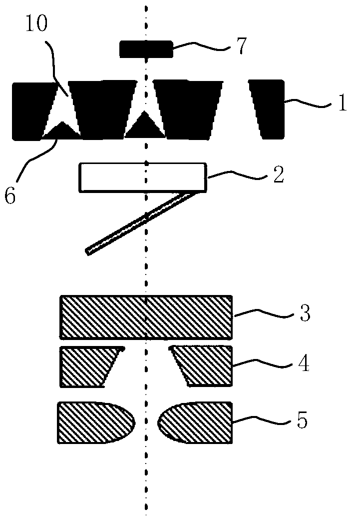
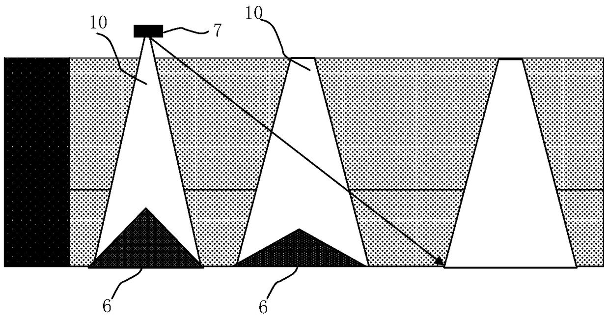
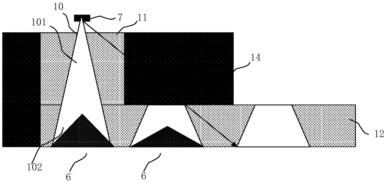
[0033] image 3 It is a schematic diagram of the split primary collimator structure and ray path of the present invention.

[0034] See image 3 , the split primary collimator provided by the present invention separates the upper half of the primary collimator from the lower half, and divides it into a fixed part 11 with a first through hole 101 and a movable part with a plurality of second through holes 102 part 12, the second through hole 102 is an empty hole or is provided with a leveler 6; The first through hole 101 and the second through hole 102 are matched, and combined to form a beam limiting hole 10 for the radiation beam to pass through. Preferably, both the first through hole 101 and the second through hole 102 are conical holes, and the first through hole 101 and the second through hole 102 are matched and combined to form the conical bea...


PUM


Abstract

The invention discloses a split type primary collimator. The split type primary collimator comprises a fixing part possessing a first through hole and a movable part possessing a plurality of second through holes, the first through hole and the second through hole match with each other, and are combined to form a beam limiting hole through which a ray beam passes. The split type primary collimator provided by the invention is divided into an upper-half fixing part and a lower-half movable part, the upper-half fixing part of the primary collimator is universal and matches different lower-half movable parts, so that the different requirements for the primary collimator and for flattening filtering the ray beam are satisfied at treatment, and accordingly, the shielding effect can be improved substantially, the manufacture materials are saved, and the primary collimator is easy to adjust and switch to support different radiotherapy modes.

Description

technical field [0001] The invention relates to a radiation head collimator, in particular to a split-type primary collimator. Background technique [0002] The radiation head of the medical electron linear accelerator is located below the accelerating tube, which provides radiation beams that meet certain uniformity and symmetry requirements, and limits the radiation beams to a certain area to obtain radiation fields of different sizes required by clinical practice. Such as figure 1 As shown, a typical radiation head consists of primary collimator 1, beam leveling filter assembly, ionization chamber 2, radiation field optical simulation system (simulating lamp and reflector), upper collimator 3, lower collimator 4 and multiple Composed of leaf gratings 5, the beam leveling filter component is mainly a leveler 6, which can be built in the primary collimator 1. For example, Siemens adopts the design of building the leveler into the primary collimator, which can increase the...

Claims


Application Information

Patent Timeline
Patent Type & Authority Patents(China)
IPC IPC(8): G21K1/02
CPCG21K1/02
Inventor 刘艳芳李贵周婧劼刘娟
Owner SHANGHAI UNITED IMAGING HEALTHCARE
Why Eureka
Try Eureka