Lead mounting device and lead mounting method of concealed and buried wiring pipe

A technology for pipe threading and wire pipe is applied in the field of buried wire pipe threading devices, which can solve the problems of large labor cost consumption, inability to reuse steel wires, waste of steel wires and iron wires, etc., and achieves low input cost and waste. Reusable, easy to bend effect

Inactive Publication Date: 2015-07-22
SHAANXI PROVINCE IN THE THIRD CONSTR CO IN THE FOURTH BRANCH
View PDF9 Cites 1 Cited by
  • Summary
  • Abstract
  • Description
  • Claims
  • Application Information

AI Technical Summary

Problems solved by technology

In actual construction, the above-mentioned traditional method of threading wires for buried electric pipes has the following defects: first, the consumption of labor costs is large, the operation is difficult, the process is complex, labor-intensive and time-consuming; second, the consumption of materials is large, which is mainly reflected in: Manual threading needs to dredge and clean the pipe with steel wire first, and then use iron wire to thread the lead wire
And the steel wire cannot be used repeatedly, resulting in a large amount of waste of steel wire and iron wire
In addition, there is still a method of using an air compressor to blow the pipe at present, but it is limited to using an air compressor to blow the pipe to complete the dredging of the pipeline; time consuming

Method used


Image

  • Lead mounting device and lead mounting method of concealed and buried wiring pipe
  • Lead mounting device and lead mounting method of concealed and buried wiring pipe
  • Lead mounting device and lead mounting method of concealed and buried wiring pipe

Examples


Embodiment Construction

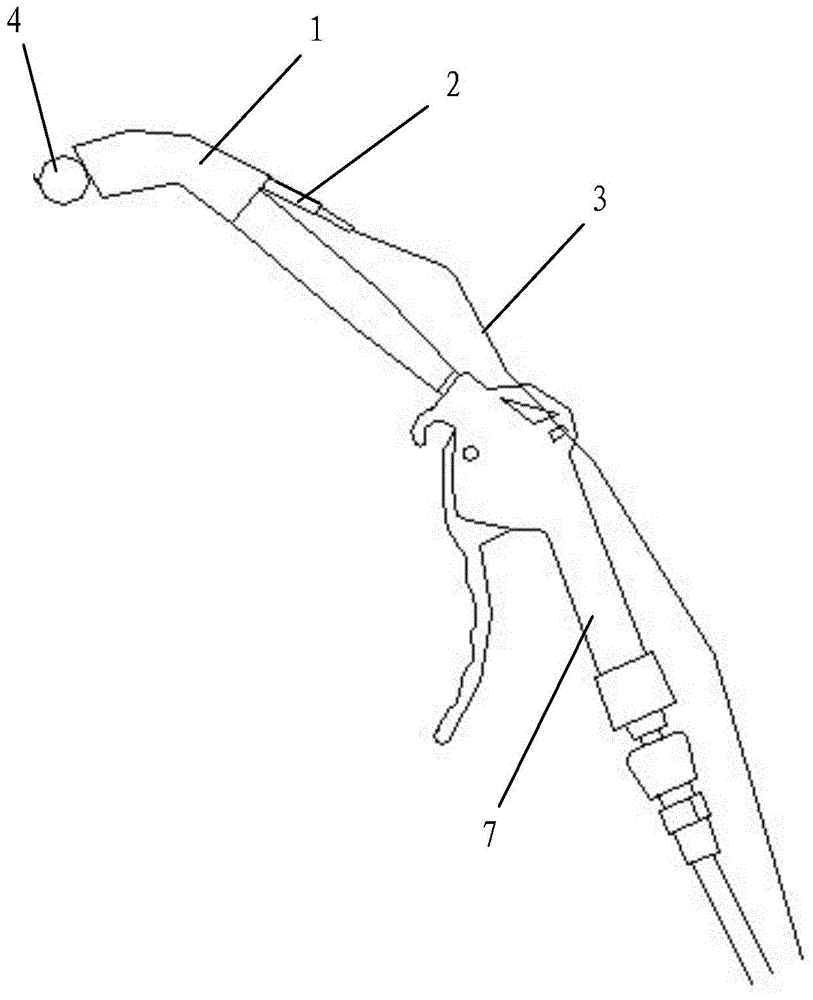
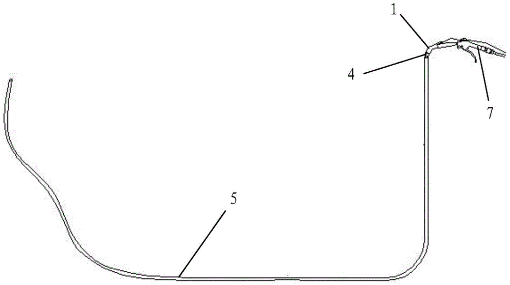
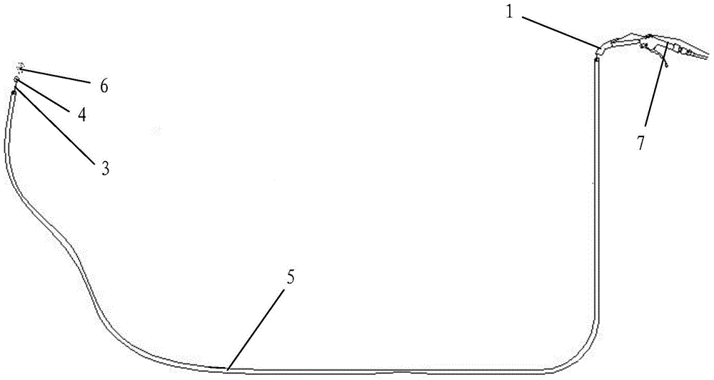
[0041] Such as figure 1 Shown is a concealed wire pipe threading device, including a gun head elbow 1 and a wire guide 2 installed on the gun head elbow 1, the gun head elbow 1 is installed in the air compressor from front to back The elbow on the muzzle of the air gun 7. The front part of the thread guide 2 is inserted into the gun head elbow 1 from back to front. The thread guide 2 has a lead channel for the lead wire 3 to pass through, and the lead channel communicates with the inside of the gun head elbow 1 , The front end of the lead wire 3 passes through the lead channel from back to front and an elastic ball 4 is fixed at its front end, the diameter of the elastic ball 4 is larger than the inner diameter of the buried wire tube 5; 1 is fixed on the muzzle of the air gun 7 with adhesive tape, and the thread guide 2 is fixed between the elbow 1 of the gun head and the muzzle of the air gun 7.

[0042] In this embodiment, the gun tip elbow 1 is an L-shaped elbow.

[0043] In ...


PUM


Abstract

The invention discloses a lead mounting device and a lead mounting method of a concealed and buried wiring pipe. The lead mounting device comprises a gun head elbow and a lead guide device installed on the gun head elbow, wherein the gun head elbow is installed on an air gun muzzle of an air compressor from front to back; the front part of the lead guide device is inserted into the gun head elbow from back to front; the lead guide device is internally provided with a lead channel through which a lead passes; the lead channel is communicated with the interior of the gun head elbow; the front end of the lead passes through the lead channel from back to front, and an elastic ball is fixed at the front end of the lead, and the diameter of the elastic ball is greater than the inner diameter of the concealed and buried wiring pipe. The lead mounting method comprises the following steps: firstly, installing the lead mounting device; secondly, regulating the air exhaust pressure of the air compressor; thirdly, mounting a lead in the following way: putting a rubber ball in place, aligning an air gun, mounting the lead and dredging the wiring pipe synchronously. According to the invention, the design is reasonable, the installation and operation are simple and convenient, the use effect is good, the lead mounting process of the concealed and buried wiring pipe can be completed simply, conveniently and rapidly, and the pipeline dredging can be completed as well as the thread is pulled.

Description

Technical field [0001] The invention belongs to the technical field of pipe threading and dredging, and in particular relates to a threading device and a method for threading a buried electric wire tube. Background technique [0002] In the construction of electrical installation engineering, the wire pipe is usually threaded first, and then the wire is pulled into the wire pipe through the lead wire. In actual threading, it is extremely difficult to thread the lead if there are many elbows in the wire tube, the diameter of the tube is thin, or there are flattened or bent parts; especially when threading the lead in a buried wire tube, it is more difficult. At the same time, before threading the wire, the wire tube must be dredged, otherwise the threading cannot be completed. Nowadays, when threading concealed electric wires and tubes, the traditional method of threading is to first manually dredge the electric wires with iron wires to complete the pipeline cleaning, and then ma...

Claims


Application Information

Patent Timeline
Patent Type & Authority Applications(China)
IPC IPC(8): H02G1/08
Inventor 张军李琪郭杰王萌王高产马宇飞薛钊赵强杜普旭梁晨旭赵帆刘书雷朱胤纲
Owner SHAANXI PROVINCE IN THE THIRD CONSTR CO IN THE FOURTH BRANCH
Why Eureka
Try Eureka