
Annular stack of laminations comprised of single-tooth stacks and method of manufacturing a stack of lamination

A laminated stack and single-tooth technology, applied in chemical instruments and methods, manufacturing motor generators, manufacturing stator/rotor bodies, etc., can solve problems such as chip short circuit, and achieve easy assembly, excellent electrical and/or geometric performance Effect

Active Publication Date: 2015-07-22
KIENLESPIESS GMBH
View PDF6 Cites 5 Cited by
  • Summary
  • Abstract
  • Description
  • Claims
  • Application Information

AI Technical Summary

Problems solved by technology

Chips can cause short circuits when the stack is inserted into electrical equipment

Method used


Image

  • Annular stack of laminations comprised of single-tooth stacks and method of manufacturing a stack of lamination
  • Annular stack of laminations comprised of single-tooth stacks and method of manufacturing a stack of lamination
  • Annular stack of laminations comprised of single-tooth stacks and method of manufacturing a stack of lamination

Examples


Embodiment Construction

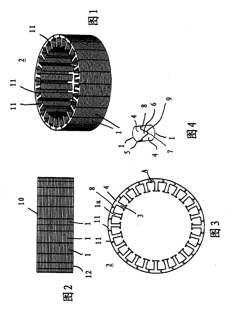
[0032] An annular lamination stack is formed of the single-tooth-shaped laminations described below, and is applied to an electric motor. Lamination stacks of this type are used, for example, in rotors and / or stators of electric motors.

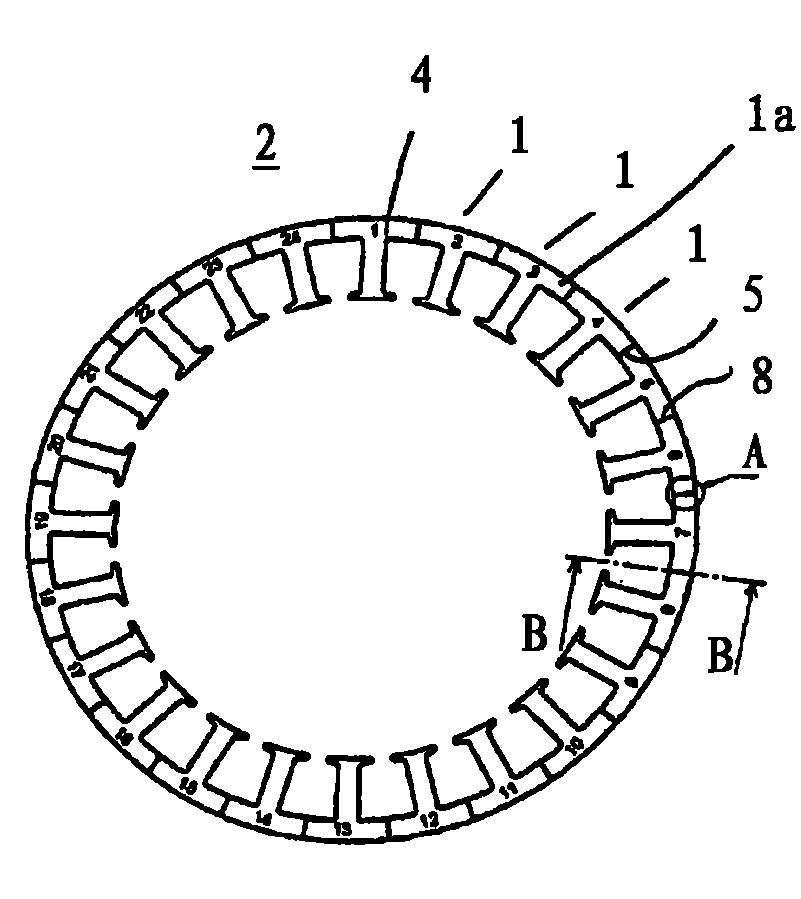
[0033] The laminations described below are single teeth which form a ring. The punched-out rings are then assembled to form an annular lamination stack 2, which consists of a set of single teeth 1 lying against each other. Their reference numbers are, for example, Figure 5 shown. according to Figure 5 In the described embodiment, the annular lamination set 2 consists of 24 single tooth sets 1 . For transport to the user, the single-tooth set 1 is assembled into an annular lamination set 2 . The user separates the annular lamination set 2 into the single tooth set 1 for wrapping and winding. The single tooth set 1 is then reassembled to form the lamination set 2 in the previous sequence. The single-tooth sets 1 are designed so that th...


PUM


Abstract

The annular stack of laminations provides adjoined single-tooth stacks, each exhibiting a pole body and a pole shoe. Adjacent single-tooth stacks abut against each other with the faces of their pole shoes. Adjacent single-tooth stacks are joined together by at least one adhesive bond in such a way that the adhesive bond can be dissolved by applying a force so as to detach the single-tooth stacks from the annular stack of laminations. While manufacturing the stack of laminations, an adhesive is at least partially introduced between the single-tooth stacks. The single-tooth stacks can be detached from the annular stack of laminations by the user for coating and winding purposes. The adhesive bond ensures that the single-tooth stacks are reliably held together during transport.

Description

technical field [0001] The invention relates to an annular lamination stack as claimed in the preamble of claim 1 and a method for producing such a lamination stack as claimed in the preamble of claim 7 . Background technique [0002] It is known that single-tooth sets made of single-tooth laminations are combined to form an annular lamination set. In order that the single-tooth set can be combined into an annular lamination set, the pole pieces of the single-tooth set have a defined contact surface, preferably a protrusion on one end face thereof and a recess complementary to the protrusion on its opposite end face. The protrusions are formed to be partially circular in front view and extend over 180°. When assembled, the single-tooth group inserts its protrusion on one end of the single-tooth group into the corresponding concave part of the adjacent single-tooth group and moves in the longitudinal direction of the single-tooth group until the combined and connected single...

Claims


Application Information

Patent Timeline
Patent Type & Authority Applications(China)
IPC IPC(8): H02K1/08H02K15/02B32B1/00
CPCH02K1/06H02K1/14B32B37/18H02K15/02B32B2457/00B32B37/1292H02K2201/09B32B38/0004H02K1/08H02K15/022H02K1/148Y10T156/1062
Inventor G·布克哈特
Owner KIENLESPIESS GMBH
Learn More