
Cooling and dehumidifying device and converter applying it

A cooling and dehumidification, converter technology, applied in the direction of output power conversion device, power electronics modification, cooling/ventilation/heating transformation, etc., can solve the problems of large heat dissipation power, large energy consumption, temperature dead angle, etc., to achieve air Uniform flow, prolong service life, avoid coagulation effect

Active Publication Date: 2017-09-22
CSR ZHUZHOU ELECTRIC LOCOMOTIVE RES INST
View PDF7 Cites 0 Cited by
  • Summary
  • Abstract
  • Description
  • Claims
  • Application Information

AI Technical Summary

Problems solved by technology

In addition, when the converter cabinet is large, it is inevitable that there will be temperature dead angles. To keep the temperature in the entire converter cabinet consistent, it needs to consume a lot of heat dissipation power and consume a lot of energy.

Method used


Image

  • Cooling and dehumidifying device and converter applying it
  • Cooling and dehumidifying device and converter applying it
  • Cooling and dehumidifying device and converter applying it

Examples


Embodiment Construction

[0031] The present invention will be further described below in conjunction with accompanying drawing.

[0032]The particulars presented here are exemplary and used for illustrative discussion of embodiments of the invention only, and are presented to provide what is believed to be the most useful and understandable description of the principles and conceptual aspects of the invention. Regarding this point, there is no attempt to introduce the structural details of the present invention beyond the level required for a basic understanding of the present invention. Those skilled in the art can clearly understand how to implement the present invention in practice through the description and accompanying drawings. Several forms.

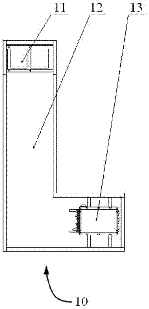
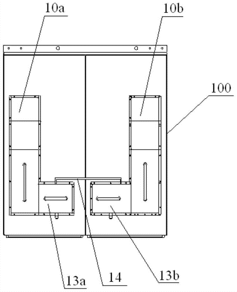
[0033] figure 1 A cooling and dehumidifying device 10 according to the present invention is shown. The device 10 includes a cooling air duct assembly, and the cooling air duct assembly includes a fan 11 , an evaporator 13 and an air duct 12 formed betw...


PUM


Abstract

The invention discloses a cooling and dehumidifying device and a converter applying the same. The cooling and dehumidifying device comprises a cooling air passage component, and the cooling air passage component comprises a fan, an evaporator and an air passage formed between the fan and the evaporator, wherein the air passage is used for cooperating with the inside of an electrical cabinet, to be cooled and dehumidified, to form a circulating air passage, and the evaporator is filled with cooling media for cooling and dehumidifying the inside of the electrical cabinet. The cooling and dehumidifying device has the advantages that on the premise of meeting cooling power requirements, good cooling and dehumidifying effects and constant-temperature constant-humidity control for the inside of the electrical cabinet can be achieved by adjusting the outside cooling media, and unsusceptibility of environment temperature and humidity in the cabinet to outside environment temperature and humidity is guaranteed, so that service life of components and parts in the cabinet is prolonged, and working reliability of electric appliances is guaranteed sufficiently.

Description

technical field [0001] The invention relates to the field of electrical equipment, in particular to a cooling and dehumidification device and a converter. Background technique [0002] At present, cooling methods of existing heat dissipation devices mainly include natural heat dissipation, forced air cooling, and cooling medium heat dissipation. [0003] Among them, since natural heat dissipation requires a spacious heat dissipation environment, it is necessary to add a larger opening area to the electrical appliance shell to reduce the protection level of the electrical appliance shell; Appropriate heat exchange fan, but when the heating power is high, it is necessary to choose a larger volume of centrifugal fan to meet the requirements of use, which increases the size and cost of the heat sink; the use of cooling media to dissipate heat can generally achieve higher The heat dissipation efficiency is high, and the heat dissipation method is simple and practical, and the re...

Claims


Application Information

Patent Timeline
Patent Type & Authority Patents(China)
IPC IPC(8): H02M1/00H05K7/20
CPCH02M1/00H05K7/20909
Inventor 冯江华尚敬胡家喜李宇王婷俞鹏程李彦涌梁志伟刘雨欣从静杨卓黄启钊
Owner CSR ZHUZHOU ELECTRIC LOCOMOTIVE RES INST
Learn More