Sliding mode control method used for two-stage DC/DC (direct current/direct current) converter

A control method and converter technology, which can be applied in the direction of conversion equipment, output power conversion device, electrical components, etc. with intermediate conversion to AC, and can solve the problems of poor robustness and low stability.

Inactive Publication Date: 2015-07-22
HUBEI SANJIANG AEROSPACE WANFENG TECH DEV
View PDF4 Cites 6 Cited by
  • Summary
  • Abstract
  • Description
  • Claims
  • Application Information

AI Technical Summary

Problems solved by technology

[0006] In view of the above defects or improvement needs of the prior art, the object of the present invention is to provide a sliding mode control method for a two-stage DC / DC converter, wherein by improving the relationship between key physical quantities and control parameters, it is compared with the current Compared with the existing technology, it can effectively solve the problems of low stability and poor robustness of the control method of the existing two-stage DC / DC converter (the former stage is a BUCK circuit, and the latter stage is a half-bridge circuit), and the sliding mode control The method is suitable for two-stage DC / DC converters with constant frequency, further expanding the application range of two-stage DC / DC converters

Method used


Image

  • Sliding mode control method used for two-stage DC/DC (direct current/direct current) converter
  • Sliding mode control method used for two-stage DC/DC (direct current/direct current) converter
  • Sliding mode control method used for two-stage DC/DC (direct current/direct current) converter

Examples


Embodiment 1

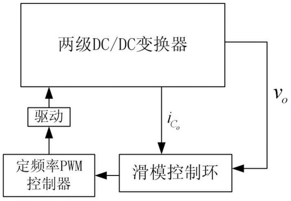
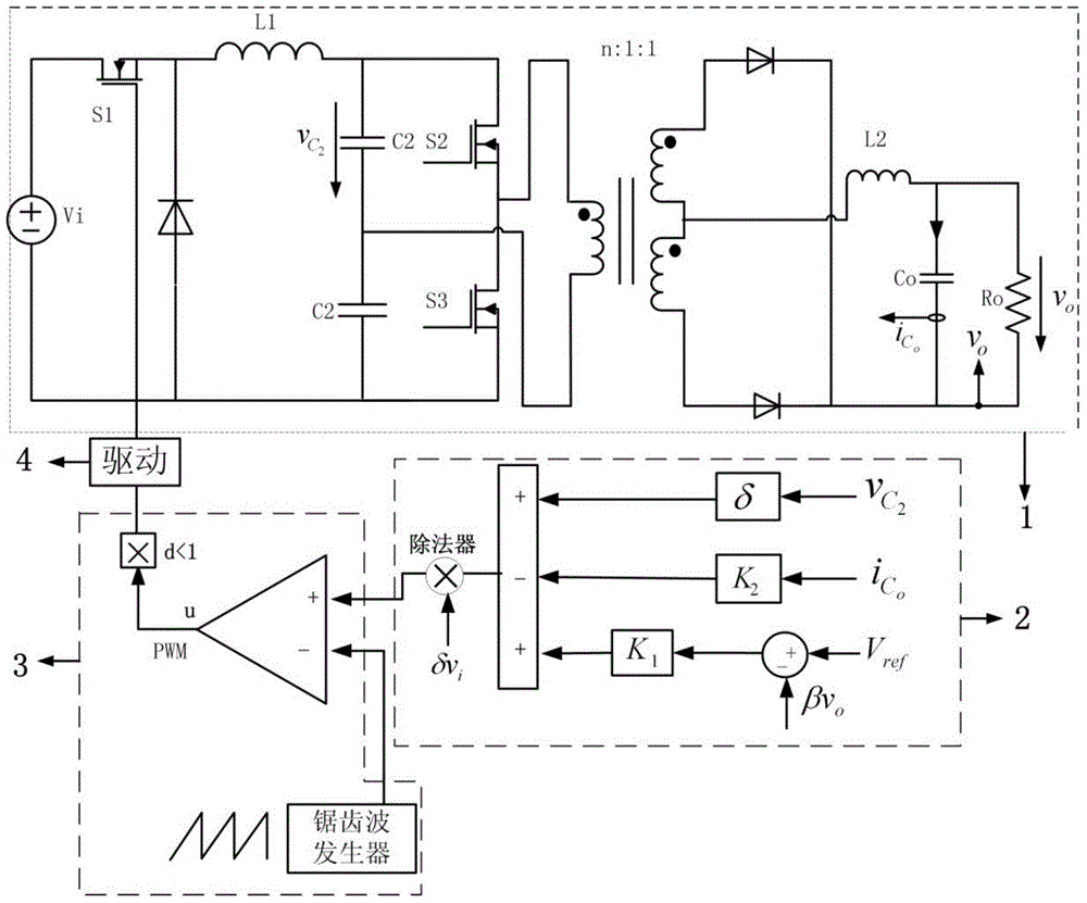
[0058] figure 1 , 2 Shown are the structural block diagram and circuit structural diagram of the sliding mode controller for the two-stage DC / DC converter of the present invention. The front stage of the two-stage DC / DC converter is a BUCK circuit, and the rear stage is a half-bridge circuit. The front-stage circuit and the rear-stage circuit are coupled through a transformer; the voltage input terminal of the two-stage DC / DC converter is on the BUCK circuit, and the input voltage is v i , and controls v through switch S1 i Whether it is connected to the two-stage DC / DC converter; the voltage output terminal is on the half-bridge circuit, and the output voltage is v o . like figure 2 As shown, the sliding mode controller for the two-stage DC / DC converter includes a main circuit 1 of the two-stage DC / DC converter, a sliding mode control loop 2, a PWM generating module 3, and a driving module 4, and its control method Include the following steps:

[0059] In step S201, t...


PUM


Abstract

The invention discloses a sliding mode control method used for a two-stage DC / DC (direct current / direct current) converter. A BUCK circuit is the front stage of the two-stage DC / DC converter, and a half-bridge circuit is the back stage of the DC / DC converter. The sliding mode control method includes the steps of establishing a state model of the two-stage DC / DC circuit; constructing a sliding mode surface function S according to the state model; obtaining equivalent control input ueq according to the S; obtaining a control signal vc of a fixed-frequency PWM (pulse-width modulation) controller and a fixed frequency sawtooth signal Vramp according to the ueq so as to achieve sliding mode controlling. The sliding mode control method is used for the two-stage DC / DC converter with the BUCK circuit serving as the front stage and the half-bridge circuit serving as the back stage and is high in controlling stability, the DC / DC converter is good in nonlinear characteristics, and roughness of parameters can be improved in presence of external disturbance; the sliding mode control method is also applicable to constant-frequency two-stage DC / DC converters and good in nonlinear control effect.

Description

technical field [0001] The invention belongs to the field of DC / DC converters and control methods thereof, and more specifically relates to a fixed-frequency sliding mode control method for two-stage DC / DC converters. Background technique [0002] The two-stage DC / DC converter with a BUCK converter in the front stage and a half-bridge in the rear stage is used in the DC / DC conversion field of high voltage input, low voltage, and high current output, such as communication power supply, aerospace power supply and vehicle power supply. more and more widely. [0003] In the existing two-stage DC / DC converter, the transfer function related to the dynamic characteristics is a fourth-order function, which has poor stability; at the same time, the characteristics and parameters of the converter itself are uncertain under nonlinear conditions. The current conventional linear control method must have a detailed understanding of the DC / DC converter and the precise adjustment of the sy...

Claims


Application Information

Patent Timeline
Patent Type & Authority Applications(China)
IPC IPC(8): H02M3/28
CPCH02M3/28H02M1/007
Inventor 乔洪涛马高育程友信常超陈圣荣王莉汪庆
Owner HUBEI SANJIANG AEROSPACE WANFENG TECH DEV
Why Eureka
Try Eureka