A Modular Multilevel Converter Sub-module Topology

A modular multi-level, topological structure technology, applied in the direction of converting AC power input to DC power output, electrical components, emergency protection circuit devices, etc., can solve the problem of overcurrent and overvoltage of converter valve components, increase equipment rating parameters, slow mechanical response, etc., to achieve the effect of reducing fault current, suppressing fault current, and saving components

Inactive Publication Date: 2018-02-09
STATE GRID CORP OF CHINA +3
View PDF3 Cites 0 Cited by
  • Summary
  • Abstract
  • Description
  • Claims
  • Application Information

AI Technical Summary

Problems solved by technology

In overhead line transmission, the traditional half-bridge structure essentially lacks DC fault isolation capability: when a fault occurs on the DC side, the anti-parallel freewheeling diode of the fully-controlled switching device easily constitutes an energy feed directly connected to the AC system at the fault point The circuit must be cut off by jumping off the AC circuit breaker. The disadvantage is that the mechanical response is slow (2 to 3 cycles are required at the fastest), which affects the normal transmission of power, and may cause overcurrent and overcurrent of the converter valve device. overvoltage
Auxiliary measures such as increasing the rated parameters of the equipment and configuring high-speed bypass switches are often required. Therefore, this topology is not suitable for power transmission on overhead lines that are prone to temporary faults such as flashovers, and it is necessary to lay cables that are expensive and have a low failure rate. line

Method used


Image

  • A Modular Multilevel Converter Sub-module Topology
  • A Modular Multilevel Converter Sub-module Topology
  • A Modular Multilevel Converter Sub-module Topology

Examples


Embodiment Construction

[0025] Below in conjunction with embodiment the present invention will be further described.

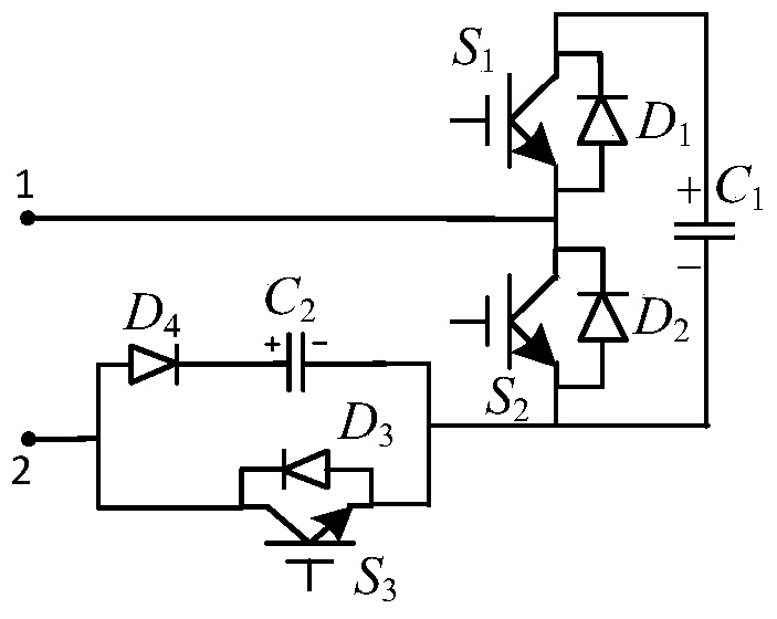
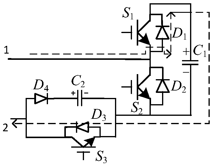
[0026] figure 1 is the topology of the improved modular multilevel converter sub-model proposed by the present invention. Among them, two terminals are connected in series, and a module is connected in parallel with the IGBT by the capacitor diode in series. When this structure is working normally, the IGBT connected in series at the two terminals is always on, and the capacitor is short-circuited. The original half-bridge sub-module structure is controlled according to the original control method, without changing the original modulation method, and the output of the sub-module is also controlled. Voltage has no effect. When a fault occurs on the DC side, the IGBTs connected in series at 2 terminals are turned off.

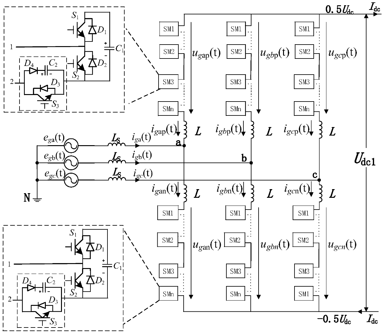
[0027] figure 2 It is a three-phase modular multi-level converter structure, each sub-module consists of figure 1 The improved sub-module composition shown.

[0...


PUM


Abstract

The present invention proposes an improved structure of a modular multilevel converter sub-module, including a first switch module and a second switch module connected in series, the negative pole of the first switch module is connected to the positive pole of the second switch module; the first capacitor The positive pole of the first capacitor is connected to the positive pole of the first switching module, the negative pole of the first capacitor is connected to the negative pole of the second switching module; the negative pole of the third switching module is connected to the negative pole of the second switching module, and the third switching module is composed of a current limiting device and a switching device Composed in parallel, the switching device is composed of insulated gate bipolar transistors and diodes connected in antiparallel, and the current limiting device is composed of capacitors and diodes connected in series. The invention is mainly applied to high-voltage and large-capacity modular multilevel converters. When the DC side fails, it can effectively block the DC fault current, better realize fault isolation, and does not need AC circuit breaker action at the same time. . The invention has a simple structure and has fast fault recovery capability after the fault is cleared.

Description

technical field [0001] The invention relates to the technical field of electric power transmission and distribution, and relates to a novel sub-module topology of a modular multilevel converter. Background technique [0002] Flexible DC transmission technology provides new means and technical solutions for solving the grid-connected bottleneck of renewable energy such as large-scale wind farms, and for the expansion and transformation of urban high-voltage power grids, grid interconnection and island power supply. The strategic choice of the power grid development pattern has been included in the "National Energy Science and Technology "Twelfth Five-Year" Plan" key equipment for high-performance power transmission and transformation, and is a major technical equipment that requires key technological breakthroughs. [0003] Since flexible direct current transmission is developed on the basis of conventional direct current transmission, in addition to the advantages of convent...

Claims


Application Information

Patent Timeline
Patent Type & Authority Patents(China)
IPC IPC(8): H02M7/483H02M1/32H02H7/122
CPCH02H7/122H02M1/32H02M7/483H02M1/325
Inventor 梅军马天郑建勇缪惠宇杜晓舟吉宇
Owner STATE GRID CORP OF CHINA
Why Eureka
Try Eureka