Assembling die and flanging manufacturing process

A technology of combining molds and manufacturing processes, applied in metal rolling and other directions, can solve problems such as low product quality, and achieve the effects of high production efficiency, improved flatness, and improved dimensional accuracy

Active Publication Date: 2015-07-29
SHANXI DOUBLE RING HEAVY MACHINERY CO LTD
View PDF7 Cites 6 Cited by
  • Summary
  • Abstract
  • Description
  • Claims
  • Application Information

AI Technical Summary

Problems solved by technology

[0004] The purpose of the present invention is to provide a combined mold and flange manufacturing process to solve the technical problem of low product quality in the traditional manufacturing process existing in the prior art

Method used


Image

  • Assembling die and flanging manufacturing process
  • Assembling die and flanging manufacturing process
  • Assembling die and flanging manufacturing process

Examples


Embodiment 1

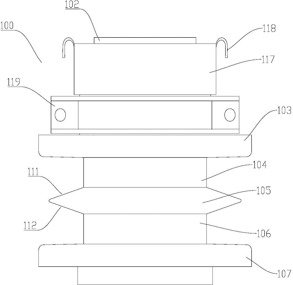
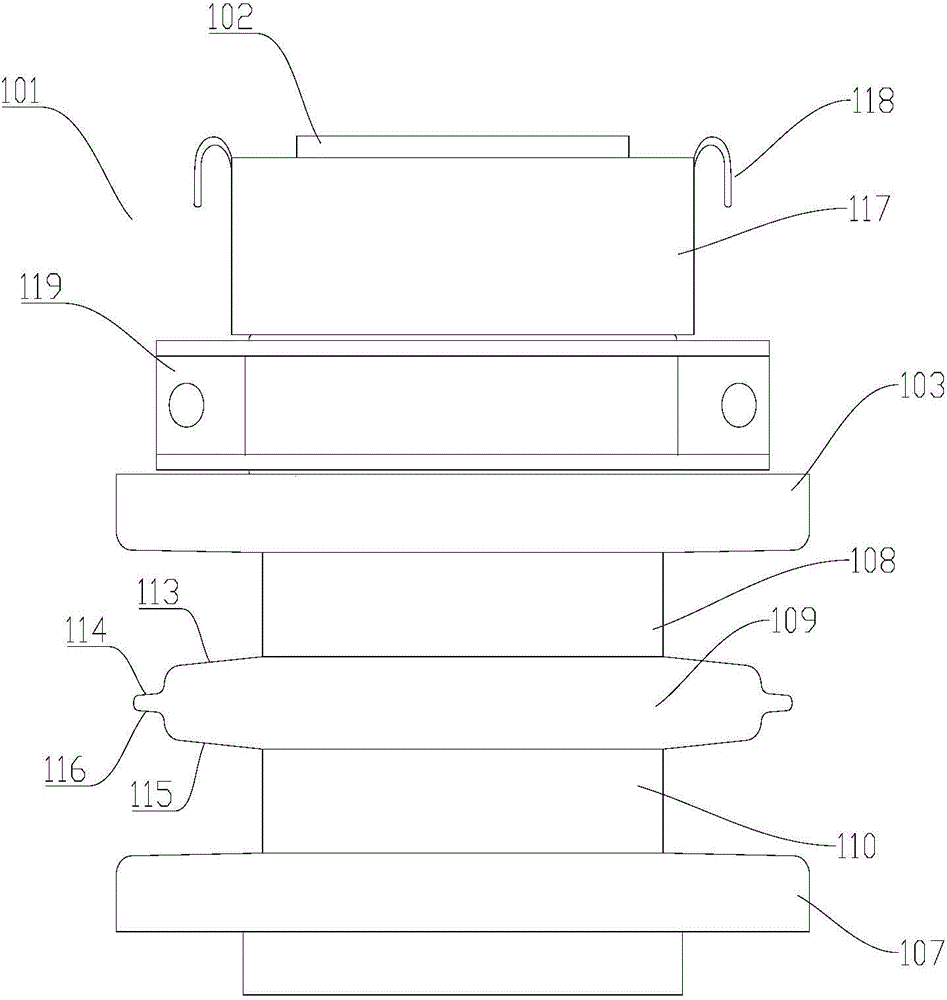
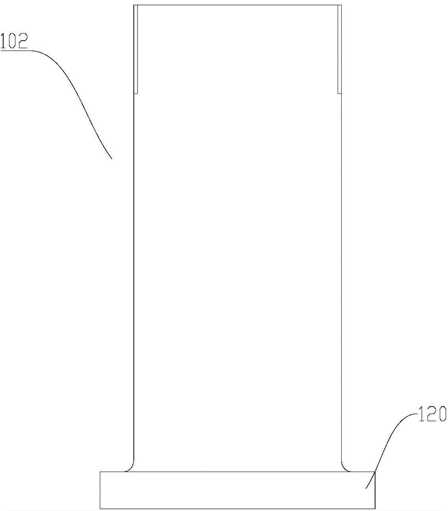
[0047] figure 1 It is a schematic structural view of the preforming mold in the combined mold provided by Embodiment 1 of the present invention, figure 2 It is a schematic structural view of the forming die in the combined die provided in Embodiment 1 of the present invention, image 3 For the structural schematic diagram of the quick-change cylinder in the combined mold provided by Embodiment 1 of the present invention, see Figure 1 to Figure 3As shown, Embodiment 1 of the present invention provides a combined mold, including: a preforming mold 100, which is used to carry out radial preforming rolling on the inner wall of the ring flange blank by using a half-open and half-closed hole type; a forming mold 101, It is used for radial forming rolling of the inner wall of the ring flange blank with a half-open and half-closed pass. The pre-forming mold includes: a quick-change cylinder 102, and the quick-change cylinder 102 is sequentially provided with an upper baffle 103, a...

Embodiment 2

[0055] Figure 4 The flow chart of the flange manufacturing process provided by Embodiment 2 of the present invention, Figure 5 It is a schematic diagram of the structure of the ring rolling machine without a combined mold in the flange manufacturing process provided by Embodiment 2 of the present invention, Figure 6 A schematic structural view of the mandrel of the ring rolling machine in which the preforming die is set in the flange manufacturing process provided by Embodiment 2 of the present invention, Figure 7 A structural schematic diagram of radial preforming rolling in the flange manufacturing process provided by Embodiment 2 of the present invention, Figure 8 For the structural diagram of radial forming rolling in the flange manufacturing process provided by Embodiment 2 of the present invention, see Figure 4 to Figure 8 As shown, the second embodiment discloses a flange manufacturing process, which includes the following steps:

[0056] Step S300, taking the ...


PUM


Abstract

The invention relates to the technical field of wind power flange manufacturing, in particular to an assembling die and a flanging manufacturing process. The assembling die comprises a preforming die and a forming die, wherein the preforming die is used for performing radial preforming rolling on the inner wall of an annular flange blank by adopting a semi-closure hole pattern; the forming die is used for performing radial forming rolling on the inner wall of the annular flange blank by adopting the semi-closure hole pattern; the preforming die comprises a quick-changing barrel; an upper baffle, an upper pre-die, a pre-cutting knife, a lower pre-die and a lower baffle sleeve the quick-changing barrel from top to bottom in sequence; the forming die comprises the quick-changing barrel; the upper baffle, an upper main die, a main cutting knife, a lower main die and a lower baffle sleeve the quick-changing barrel from top to bottom in sequence. The assembling die and the flanging manufacturing process disclosed by the invention, dimensional accuracy of rolling and ring rolling is increased, the flatness of the end face of a product can be conveniently controlled, and is increased; the product material and cost are reduced, and manufacturing is time-saving and labor-saving; the energy consumption of the process is low, the production efficiency is high, and the product quality is improved.

Description

technical field [0001] The invention relates to the technical field of wind power flange manufacturing, in particular to a combined mold and flange manufacturing process. Background technique [0002] The wind power flange is a large annular part. With the continuous increase of the capacity of the wind power generation unit, the diameter of the wind power tower continues to increase, and the wind power flange used in the wind power tower also increases accordingly. At present, the longitudinal section of the commonly used wind power flange is an L-shaped inner step cross section, and the formed product of the wind power flange has a large size and a large tonnage. [0003] At present, the traditional method of manufacturing wind power flange forming blanks is to roll and expand a single wind power flange blank with a rectangular longitudinal section through a ring rolling machine to be processed into a single wind power flange forming blank. In the traditional manufacturin...

Claims


Application Information

Patent Timeline
Patent Type & Authority Applications(China)
IPC IPC(8): B21H1/06
Inventor 王林伟智伟平张贵文高惠敏陈玉平
Owner SHANXI DOUBLE RING HEAVY MACHINERY CO LTD
Why Eureka
Try Eureka