Chain type tool magazine

A chain-type tool magazine and tool magazine technology, applied in the direction of clamping, supporting, positioning devices, etc., can solve the problems of occupying machine tool configuration space, assembling troubles, and occupying configuration space, etc., to achieve small size, easy assembly, and saving The effect of configuration space

Inactive Publication Date: 2015-07-29
邱菩宣
View PDF7 Cites 8 Cited by
  • Summary
  • Abstract
  • Description
  • Claims
  • Application Information

AI Technical Summary

Problems solved by technology

[0003] Taking the chain tool magazine as an example, it is mainly equipped with a plurality of driven sprockets and driving sprockets on the tool magazine body, and a chain with a tool holder is arranged around the driven sprockets and driving sprockets, so as to Various processing tools are mounted, and the driving chain wheel drives the chain to rotate, so that the processing tool on the tool holder is displaced to the tool outlet position of the tool magazine body, and then the processing tool is pushed out of the tool magazine body to perform the replacement Tool operation, and the tool change method of the chain tool magazine is to configure a tool change mechanism (ATC) with a tool change arm outside the tool magazine body of the chain tool magazine, and the tool change arm of the tool change mechanism The machining tools on the tool magazine and the machining spindle perform tool change operations; since the chain tool magazine mounts various machining tools on each tool holder of the chain, the length of the chain’s rotary path can be increased in a limited space. To mount more different processing tools, however, it must be equipped with a tool change mechanism for performing tool change operations. The tool change mechanism will not only occupy the configuration space on the machine tool, but also must be compatible with the tool outlet position and the tool magazine body. The processing spindle is matched with high precision, which is quite troublesome in assembly
[0004] Also take the bamboo hat tool magazine as an example, please refer to figure 1 As shown, it is provided with a processing spindle 11 on the machine tool 10, and the side of the processing spindle 11 is equipped with a hat-type tool magazine 20, and the hat-type tool magazine 20 is provided with a circular A cutter head 22 is provided for mounting various types of processing tools, and a moving device 23 is used to drive the bamboo hat type tool magazine 20 to move laterally below the processing spindle 11, so that the processing spindle 11 can directly perform tool changing operations; however, Although the bamboo hat type tool magazine 20 does not need to be equipped with a tool change mechanism, the number of processing tools that can be mounted by the bamboo hat type tool magazine 20 is limited by the circumferential length of the cutter head. For a sufficient number of processing tools, the circumferential length of the cutter head 22 must be increased, so that the overall volume of the disc tool magazine 20 is quite large, and the lack of configuration space on the machine tool is also caused.

Method used


Image

  • Chain type tool magazine
  • Chain type tool magazine
  • Chain type tool magazine

Examples


Embodiment Construction

[0045] In order to enable your examiner to have a further understanding of the present invention, the preferred embodiments are hereby given together with the accompanying drawings, and are described in detail as follows:

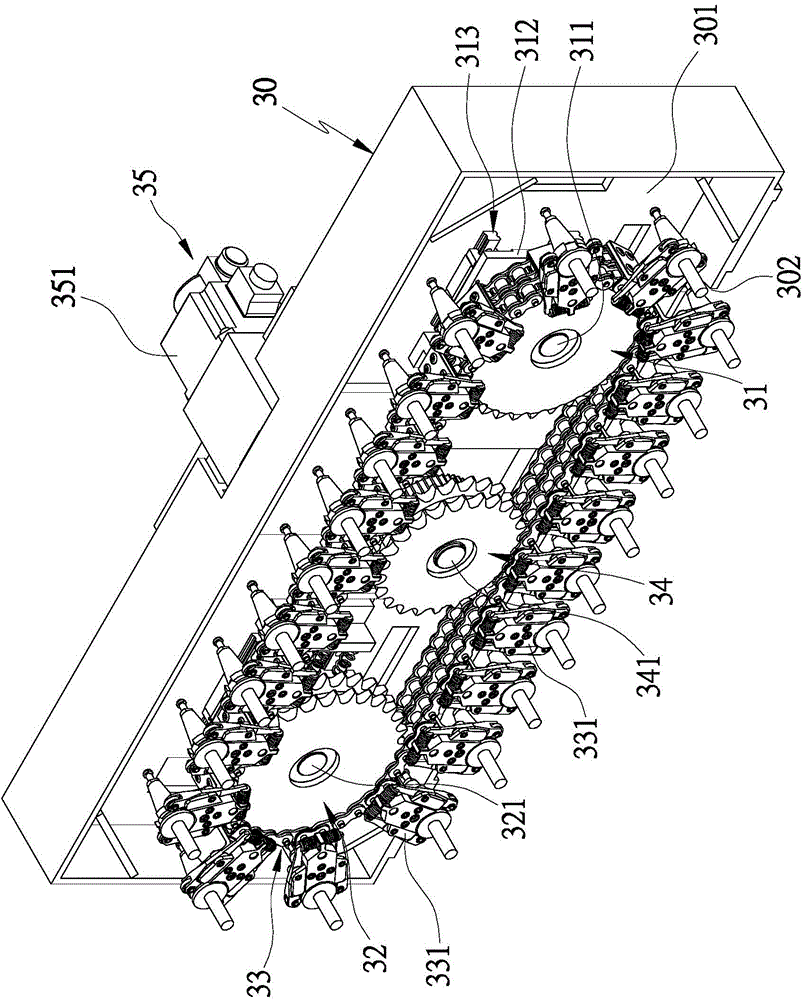
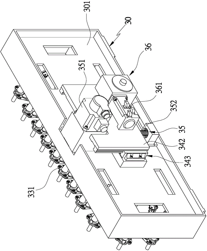
[0046] see Figure 2 to Figure 5 As shown, the chain tool magazine of the present invention is provided with a generally rectangular tool magazine body 30. The front side of the tool magazine body 30 is open, the rear side is provided with a seat plate 301, and the bottom is provided with an opening 302. The tool magazine body 30 is slidably provided with at least two driven sprockets in the horizontal direction, and an elastic push structure is provided on the two driven sprockets for elastically pushing against the two driven sprockets; in this embodiment , the tool magazine body 30 is provided with a first driven sprocket 31 and a second driven sprocket 32, the first driven sprocket 31 is pivotally mounted on the first sliding seat 312 with a first pivot 3...


PUM


Abstract

Disclosed is a chain type tool magazine. A tool magazine body is provided with at least two driven chain wheels; a chain which comprises a plurality of cutter placement frames is arranged on the driven chain wheels in a winding mode; each driven chain wheel is provided with an elastic pushing structure so as to abut against and push the driven chain wheels to be meshed with the chain; the tool magazine body is provided with a driving chain wheel; the driving chain wheel is connected with a displacement driving mechanism and a rotating driving mechanism; the driving chain wheel is driven by the displacement driving mechanism to move to be meshed with the chain to push and guide the cutter placement frames arranged on the chain to a cutter replacement position; the driving chain wheel is driven by the rotating driving mechanism to rotate to drive the rotary actuation of the chain so as to enable the preset cutter placement frames arranged on the chain to rotate into a column to the cutter replacement position. Accordingly, a sufficient number of different machining cutting tools can be placed in a straddled mode and the size of the tool magazine body is effectively reduced due to the plurality of cutter placement frames of the chain and the preset machining cutting tools arranged on the chain are driven by the pushing and guiding of the driving chain wheel to rotate into a column to the cutter replacement position and accordingly the cutter replacement operation can be directly executed through a machining main shaft and the practical benefits of the saving on the configuration space and the easy assembly are achieved.

Description

technical field [0001] The present invention provides a kind of tool holders with a chain that can set up a sufficient number of different processing tools, and effectively reduce the volume of the tool magazine body. In addition, it uses the push and drive of the driving sprocket to make the preset processing tools on the chain When the tool row is transferred to the tool change position, the tool change operation can be performed directly by the machining spindle, and the configuration space can be saved and the chain tool magazine is easy to assemble. Background technique [0002] At present, machine tools are equipped with tool magazines (such as chain tool magazines, hat-style tool magazines, etc.) to store various types of processing tools, and are used for changing the machining spindle of the machine tool to meet different job requirements. [0003] Taking the chain tool magazine as an example, it is mainly equipped with a plurality of driven sprockets and driving sp...

Claims


Application Information

Patent Timeline
Patent Type & Authority Applications(China)
IPC IPC(8): B23Q3/155
CPCB23Q3/15526B23Q3/15724B23Q3/15706Y10T483/1795
Inventor 邱菩宣
Owner 邱菩宣
Why Eureka
Try Eureka