
Welding, positioning and flaw detection method for automobile muffling pipe

A technology for mufflers and automobiles, which is applied to measuring devices, instruments, scientific instruments, etc., can solve the problems of low welding seam inspection and repair efficiency, inability to make targeted improvements, and inability to mark cracks in time, so as to improve the efficiency and convenience of flaw detection and positioning. Repair welding, convenient and quick removal effect

Inactive Publication Date: 2015-07-29
CHENGDU LINGCHUAN SPECIAL IND
View PDF0 Cites 0 Cited by
  • Summary
  • Abstract
  • Description
  • Claims
  • Application Information

AI Technical Summary

Problems solved by technology

However, due to the limitations of the welding process in the prior art, after the muffler has been used for a period of time, harsh noises will appear in the exhaust emissions of the automobile. After research, it has been found that the reason is that cracks appear in the straight weld of the outer pipe of the muffler, which in turn leads to a crack in the muffler. In the process of detecting the weld seam of the outer pipe, the water detection method is generally used, that is, the outer pipe is placed in the liquid, and then compressed air is injected into the outer pipe to observe whether there are bubbles coming out of the weld seam, but through this kind of The cracks detected by this method cannot be marked in time, that is, after they are taken out of the liquid environment, the weld can only be repaired comprehensively, and no targeted improvement can be made, which greatly reduces the efficiency of weld detection and repair

Method used


Image

  • Welding, positioning and flaw detection method for automobile muffling pipe
  • Welding, positioning and flaw detection method for automobile muffling pipe

Examples


Embodiment 1

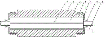
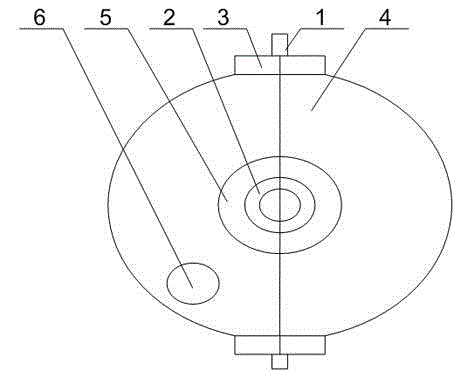
[0025] Such as figure 1 and figure 2 As shown, this embodiment includes the following steps,

[0026] (A) First place the main part of the outer tube 2 in the filling cavity, and the two ends of the outer tube 2 are fastened by the fixing ring 5;

[0027] (B) The two partition plates 1 are attached to the outer walls of the upper and lower sides of the outer tube 2 respectively, and then the movable ends of the two half cylinders 4 are connected and fixed;

[0028] (C) Start to inject gypsum slurry into the injection hole 6 until the gypsum slurry fills the cavity completely;

[0029] (D) The end of the outer tube 2 fastened by the fixing ring 5 is connected to the trachea, and the trachea injects compressed air into the outer tube 2;

[0030] The above-mentioned steps include two semi-cylindrical bodies 4 with both ends closed and hinged to each other and fixing rings 5 ​​fixed at both ends of the semi-cylindrical body 4, the fixing ring 5 is coaxial with the semi-cylindr...


PUM


Abstract

The invention discloses a welding, positioning and flaw detection method for an automobile muffling pipe. The welding, positioning and flaw detection method comprises the following steps: a main body part of an outer pipe is arranged in a filling cavity, and the two ends of the outer pipe are fastened by fixing rings; two separation plates are respectively attached to the outer walls of the upper side and the lower side of the outer pipe, and the movable ends of the two half barrel bodies are fixedly connected; gypsum slurry is injected into an injection hole until the gypsum slurry completely fills the filling cavity; the end part of the outer pipe fastened by the fixing ring is connected with an air pipe, and compressed air is injected into the outer pipe through the air pipe; under the jetting action of the compressed air, obvious recess traces are retained on a semisolid structure; the compressed air is continuously fed until the gypsum slurry is completely converted into a solid structure, and air feeding is stopped; the filling cavity is opened to separate the formed gypsum solid structure from the outer pipe and the inner walls of the half barrel bodies respectively; after an independent gypsum fixing structure is obtained, the size of an arc-shaped inner wall recess is observed, so that a crack position, corresponding to the outer pipe, of a welding line can be obtained.

Description

technical field [0001] The invention relates to the field of automobile noise reduction, in particular to a positioning flaw detection method for welding seams of automobile noise reduction pipes. Background technique [0002] Noise is generated at the intake / exhaust port of the air compressor when it is working, at the exhaust port of the car engine when it is working, and at the exhaust port of some factories. In order to eliminate these noises, mufflers are installed at the air inlet or exhaust port of these equipment or occasions. The muffler includes an outer tube and an inner tube, both of which are conical tubes with a small top and a large bottom, and the taper of the two is equal. There is a middle partition on the inner side of the upper part of the outer tube, and there is a gap between the middle partition and the upper end of the outer tube. The surrounding of the middle partition is connected with the inner wall of the outer tube. The upper end of the inner p...

Claims


Application Information

Patent Timeline
Patent Type & Authority Applications(China)
IPC IPC(8): G01N33/00
Inventor 张军叶维敏汪庭文何晓鸣杨军
Owner CHENGDU LINGCHUAN SPECIAL IND
Learn More