
Active fiber coupling device

A fiber coupling and photoelectric coupling technology, applied in the field of active fiber coupling devices, can solve problems such as difficulty in adapting to the requirements of the use environment, affecting the performance of fiber coupling, and small bearing and clamping forces, and achieves simple and reasonable structure settings and wide application range wide, improve the effect of adhesion

Active Publication Date: 2015-07-29
EVERPRO TECH COMPANY
View PDF5 Cites 14 Cited by
  • Summary
  • Abstract
  • Description
  • Claims
  • Application Information

AI Technical Summary

Problems solved by technology

The existing coupling device is limited by the structure, the bearing force and clamping force between the coupling parts are small, and it is easy to be loosened by force. When the connector is pulled and stressed, the parts will be separated, which will affect the coupling performance of the optical fiber
Because of this, the existing coupling devices are still difficult to adapt to the requirements of the use environment that requires frequent plugging and pulling
Due to the limited seismic requirements of existing coupling devices, their scope of use is still limited. Therefore, how to obtain a built-in locking function and meet the requirements of the communication electronic products for the tensile, seismic, and dustproof capabilities of the joints has become an existing Technical problems that need to be solved urgently for fiber-coupled devices in technology

Method used


Image

  • Active fiber coupling device
  • Active fiber coupling device
  • Active fiber coupling device

Examples


Embodiment Construction

[0029] The present invention will be further described in detail below in conjunction with the accompanying drawings and embodiments. It should be understood that the specific embodiments described here are only used to explain the present invention, but not to limit the present invention. In addition, it should be noted that, for the convenience of description, only some structures related to the present invention are shown in the drawings but not all structures.

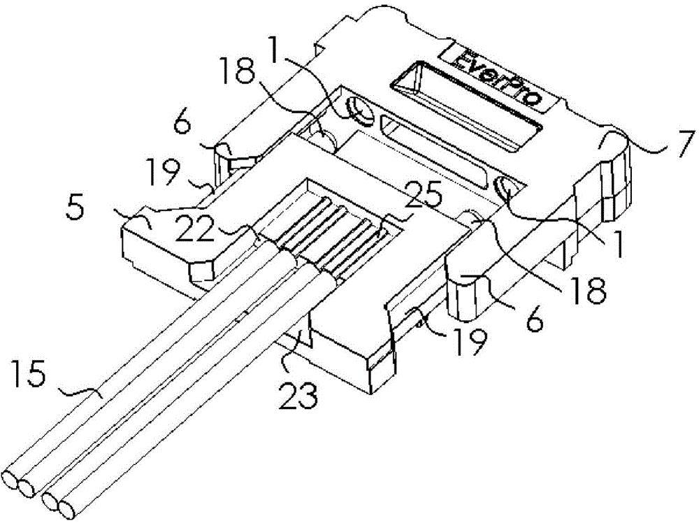
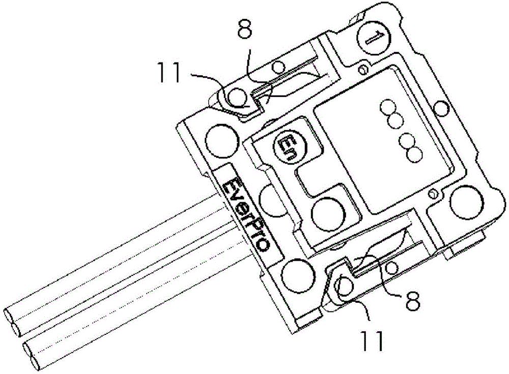
[0030] join Figure 1-3 , discloses a schematic diagram of the connection of an active optical fiber coupling device, the active optical fiber coupling device includes an optical coupling joint 7 and an optical fiber joint 5 stacked up and down, and the optical coupling joint 7 includes at least one optical device 13 and at least one optical device at the bottom The driving chip 12 exemplarily includes four optical devices 13 in the drawings, and the driving chip may also be four driving chips to respectively driv...


PUM


Abstract

An active fiber coupling device comprises an optocoupler connector and a fiber connector which are stacked vertically in a matched manner. A reflection surface of 45 degrees is arranged above an optical device, is used for converting the upwardly emitted vertical light beam of the optical device into horizontal one and is provided with a fixing hook, a connecting arm and a positioning post hole; the middle of the fiber connector is provided at least one fiber and is provided with a fixing hook, a plugging guide groove and a positioning post; when the optocoupler connector is connected to the fiber connector, the fiber and the reflection surface of 45 degrees receive the horizontal light beam oppositely, the connectors are connected mutually, the stable connection of the optocoupler connector and fiber connector is guaranteed, and corresponded movement is avoided. By the aid of the device, the entire structure is shortened, the optical path is shortened, light consumption in material is reduced, a metal buckler is omitted, cost is reduced greatly, alignment is facilitated, and the stability of the structure is improved; the device is simple and reasonable in structure, small in size, high in strength, convenient to manufacture and easy to assemble and use and has wide application range.

Description

technical field [0001] The present application relates to the field of optical fiber connectors, in particular to an optical coupling connector with a photoelectric conversion chip, and an optical fiber connector with optical fibers. The lens group connector and the optical fiber connector are connected to form an active optical fiber coupling device. Background technique [0002] With the advent of the information age in the new century, information technology affects and changes people's production methods and lifestyles, and has become an important driving force for modern economic development. Communication has penetrated into all aspects of people's work life and social economy. In this context, faster, more convenient and more practical communication connector products are the current development direction of communication connector products. [0003] Compared with traditional electrical connectors, optical fiber connectors have unique advantages such as good anti-ele...

Claims


Application Information

Patent Timeline
IPC IPC(8): G02B6/42
CPCG02B6/4204G02B6/4228
Inventor 魏立华冯汉强汤金宽
Owner EVERPRO TECH COMPANY
Learn More