Bare conductor electrified binding winder

A bare wire and wire winder technology, which is applied in the field of bare wire live bonding wire winder, can solve problems such as easy to pierce insulating gloves, vicious electric shock accidents, and low bonding efficiency

Inactive Publication Date: 2015-07-29
STATE GRID SHANDONG RONGCHENG POWER SUPPLY +1
View PDF8 Cites 3 Cited by
  • Summary
  • Abstract
  • Description
  • Claims
  • Application Information

AI Technical Summary

Problems solved by technology

However, the binding wire is long. If the binding wire is accidentally short-circuited between phases during operation, a vicious electric shock accident will occur. Therefore, the operator must wear insulating gloves during operation.
However, due to the small diameter of the binding wir...

Method used


Image

  • Bare conductor electrified binding winder
  • Bare conductor electrified binding winder
  • Bare conductor electrified binding winder

Examples


Embodiment Construction

[0015] The present invention will be further described below in conjunction with the accompanying drawings and embodiments.

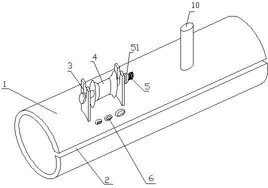
[0016] as attached figure 1 As shown, the bare wire live-bonding winding device includes a tube body 1, on which an axial wire inlet 2 is arranged, and the wire inlet 2 extends from one end of the tube body 1 to the other end.

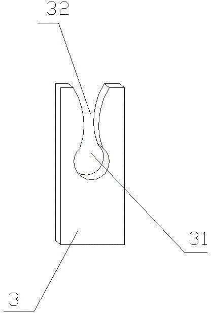
[0017] as attached figure 1 As shown, a reel stand is provided on the outer wall of the pipe near the left end of the pipe body. The reel stand includes two vertical plates 3 perpendicular to the outer wall of the pipe body. A reel 4 is arranged between the two stand plates. The two ends of wheel 4 and the wire wheel shaft are supported on the vertical plate, and the wire wheel 4 can rotate freely around the wire wheel shaft 5, and the tube body wall at the bottom of the wire wheel is provided with a binding wire entering hole 6.

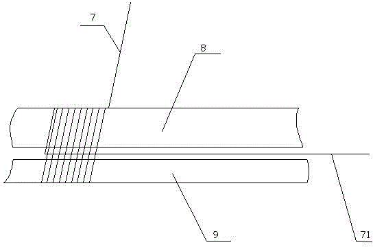
[0018] During use, the binding wire 7 is wound on the wire pulley 4, and the pipe body 1 is set ...


PUM


Abstract

The invention relates to an electric power construction device. In order to solve the technical problems existing during bared conductor binding at present, the invention provides a bare conductor electrified binding winder. The bare conductor electrified binding winder comprises a pipe body, wherein an axial wire inlet is formed in the pipe body; the wire inlet extends from one end of the pipe body to the other end of the pipe body; a wire wheel stand is arranged on the outer wall of the pipe body close to the left end of the pipe body; the wire wheel stand comprises two vertical plates perpendicular to the outer wall of the pipe body; a wire wheel is arranged between the two vertical plates; a wire wheel shaft passes through the wire wheel, and two ends of the wire wheel shaft can rotate freely around the wire wheel shaft; a binding wire incoming hole is formed in the wall of the pipe body at the bottom of the wire wheel. During conductor binding phase by phase by adopting the tool, the range of limb activities of a worker is reduced, and the occurrence of vicious personnel injury and death accidents is completely eradicated.

Description

technical field [0001] The invention relates to an electric power construction device, in particular to a wire winder for live binding of bare conductors. Background technique [0002] At present, when carrying out the downlink lead wire on the power supply line, the operation process is as follows: the downlink wire is parallel to the main power supply line and then wrapped and bound with a binding wire, and the binding length is generally 10-20cm. At present, in order to reduce the power-off time, most of the downlink operations are live operations. The operators need to step on the insulated climbing car to carry out the binding operation. Since the operation is performed with single-phase winding and binding, although the human body is charged, it will not Risk of electric shock. However, the binding wire is relatively long. If the binding wire is accidentally shorted between phases during operation, a vicious electric shock accident will occur. Therefore, the operator ...

Claims


Application Information

Patent Timeline
IPC IPC(8): H02G1/14H01R43/033
Inventor 王华军于志军钱华建李彬林春波于永鹏李先成于海燕苏家德
Owner STATE GRID SHANDONG RONGCHENG POWER SUPPLY
Why Eureka
Try Eureka