System and method supporting hybrid power/battery scheme

A battery and energy technology, applied in the field of methods and battery and energy systems, can solve problems such as inability to output high power instantaneously, difficult design/configuration, low energy density, etc., and achieve improved system efficiency, thermal risk, and long preparation time Effect

Inactive Publication Date: 2015-07-29
MEDIATEK INC
View PDF1 Cites 3 Cited by
  • Summary
  • Abstract
  • Description
  • Claims
  • Application Information

AI Technical Summary

Problems solved by technology

For example, a battery cell characterized by high power density can be used to provide or receive a high level of current instantaneously; however, such a battery cell suitable for high current charging and discharging usually has a low energy density
Conversely, a battery unit characterized by high energy density can be used to output a medium level of power stably for a long time; however, in high dynamic power applications, this kind of battery unit cannot output high power instantaneously
This makes it difficult to design / configure the battery characteristics of an electronic device that is used to perform different applications / operations that would correspond to different loads, such as a portable electronic device
For example, some applications / loads need to consume a high level of power momentarily to achieve high performance, while some applications and / loads may consume a static / moderate power for a long time

Method used


Image

  • System and method supporting hybrid power/battery scheme
  • System and method supporting hybrid power/battery scheme
  • System and method supporting hybrid power/battery scheme

Examples


Embodiment Construction

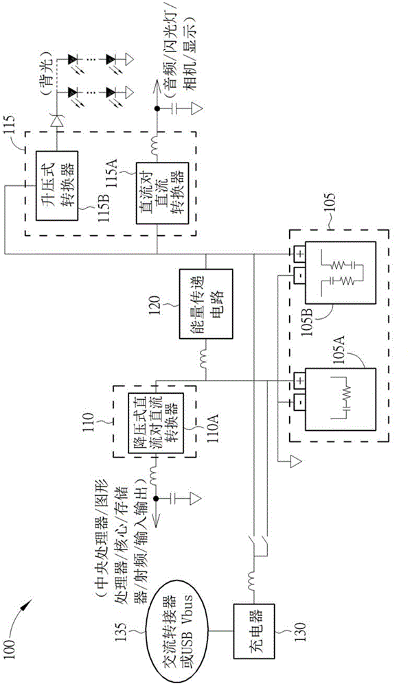
[0032] refer to figure 1 , figure 1 It is a schematic diagram of a system 100 supporting a hybrid power supply / battery technical solution according to a first embodiment of the present invention. The hybrid power / battery solution may at least provide power / energy of different power sources corresponding to different characteristics of different applications / operations of a portable device, and / or if the power source is rechargeable, suitably charge different power sources. With the hybrid power supply / battery technical solution, the system 100 can instantaneously output stronger current (that is, deliver stronger current) and higher voltage with better conversion efficiency. Thus, good system dynamic performance can be achieved while maintaining long operating / ready times with improved system efficiency.

[0033] In terms of implementation, the system 100 includes a battery 105 , at least one first power output circuit 110 , at least one second power output circuit 115 , an ...


PUM


Abstract

A system (100, 200, 300, 400, 500) consuming energy provided from a battery (105, 205, 305, 405, 505) including a first power source (105A, 205A, 305A, 405A, 505A) and a second power source (105B, 205B, 305B, 405B, 505B). It may include an energy transferring circuit (120, 320, 420, 520). The energy transferring circuit (120, 320, 420, 520) transfers power of at least one of the first and second power sources (105A, 205A, 305A, 405A, 505A, and 105B, 205B, 305B, 405B, 505B) to the other of the first and second power sources (105A, 205A, 305A, 405A, 505A, and 105B, 205B, 305B, 405B, 505B). The first power source (105A, 205A, 305A, 405A, 505A) is arranged to provide power for at least one high dynamic power operation that instantaneously consumes large currents. The second power source (105B, 205B, 305B, 405B, 505B) is arranged to provide power for at least one static/medium power operation. The first power source (105A, 205A, 305A, 405A, 505A) and the second power source (105B, 205B, 305B, 405B, 505B) are supplying the system (100, 200, 300, 400, 500) simultaneously.

Description

technical field [0001] The invention relates to a power management technical solution, especially a system, method and battery for consuming energy provided by a battery. Background technique [0002] In general, there is still a trade-off between high power density characteristics and high energy density characteristics for recently developed battery cells such as Li-ion batteries. For example, a battery cell characterized by high power density can be used to provide or receive a high level of current instantaneously; however, such a battery cell suitable for high current charging and discharging usually has a low energy density. Conversely, a battery cell characterized by high energy density can be used to output a moderate level of power stably for a long time; however, in high dynamic power applications, this type of battery cell cannot output high power instantaneously. This makes it difficult to design / configure the battery characteristics of an electronic device, suc...

Claims


Application Information

Patent Timeline
Patent Type & Authority Applications(China)
IPC IPC(8): H02J7/00
CPCH02J2007/0067H02J7/0065H02J7/0054B60L11/18H02J7/34H02J7/342H02J1/08H02J7/0019H02J7/02H02J2207/20H02J2310/48H02J7/0025
Inventor 陈碧芬
Owner MEDIATEK INC
Why Eureka
Try Eureka