A method for aligning screw bearing seat

A technology of bearing seat and lead screw, which is applied in the maintenance field of lead screw, can solve the problems of long preparation period, large impact of dial indicator, high labor intensity, etc., and achieve the effect of increasing maintenance cost, increasing preparation time and increasing labor load

Active Publication Date: 2019-03-29
CHENGDU AIRCRAFT INDUSTRY GROUP
View PDF8 Cites 0 Cited by
  • Summary
  • Abstract
  • Description
  • Claims
  • Application Information

AI Technical Summary

Problems solved by technology

[0004] 1) The pre-preparation period is long, the tools are prepared in many types, and the labor intensity is high;
[0005] 2) Due to the limitation of the range of the dial indicator frame, the distance between the screw and the guide rail is more than 400MM, and it cannot be detected;
[0006] 3) Affected by the ball groove of the screw, it has a greater impact on the dial indicator, which is easy to damage the dial indicator.
[0008] 4) Affected by the disturbance of the lead screw, the detection point cannot be accurately positioned, resulting in inaccurate detection data;
[0009] 5) Affected by inaccurate data, multiple inspections are required, and the inspection cycle is long;
[0010] 6) Affected by the screw base, the measurement range is limited
This method contains all the disadvantages of the first technology, and at the same time, it requires a lot of physical exertion due to the need to manually push the workbench to move back and forth.

Method used


Image

  • A method for aligning screw bearing seat
  • A method for aligning screw bearing seat
  • A method for aligning screw bearing seat

Examples


example

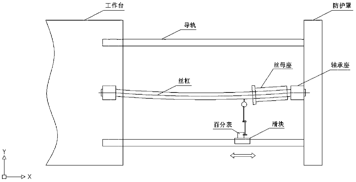
[0044] To detect the lead screw in the X direction of a certain machine tool, place the dial indicator frame on the machine tool table near the screw nut seat, and press the shift pointer of the dial indicator on the straight surface of the lead screw.

[0045] Start the machine tool to move the workbench from the left end to the right end close to the bearing seat, and record the readings of the hands.

[0046] It is found that there are errors in both the horizontal plane and the vertical plane of the right-hand screw socket, the position error of the horizontal plane is 0.3MM, and the position error of the vertical plane is 0.1MM.

[0047] To adjust the horizontal direction, attach the dial indicator frame to the bed, and the needle of the dial indicator touches the surface of the nut seat to be adjusted; loosen the fastening screw of the right end bearing seat with error, and adjust 0.3MM in the opposite direction with a jack before tightening it. solid.

[0048] The adju...


PUM


Abstract

The invention discloses a lead screw bearing block alignment method. A dial indicator frame is arranged at the position, close to a screw nut base, on a workbench, a machine tool is started, and the workbench records the read number of a pointer on the screw nut base; adjustment is conducted according to the record, the dial indicator frame is adsorbed to a lathe bed, and the pointer of a dial indicator makes contact with the surface of a nut base or the screw nut base to be adjusted; a fastening screw at the to-be-adjusted part is loosened, and the fastening screw is moved through a jack or a crowbar; when the deflection distance and the earlier-stage measuring value are the same, the fastening screw at the part is fastened; adjustment is conducted in the vertical direction, the fastening screw at the to-be-adjusted part is loosened according to the earlier-stage measuring result, and a gasket is additionally arranged to the position below the fastening screw and fastened; and the machine tool is started for rechecking. According to the lead screw bearing block alignment method, few earlier-stage preparing tools are adopted, and detection can be conducted only by preparing the ordinary dial indicator and the dial indicator frame; no requirement exists for the distance between a guide rail and a lead screw; influences from lead screw deflection are weak, and the state of the detection process and the state in the actual machine tool usage process are the same; and the influences on the measuring range from the screw nut base are weak.

Description

technical field [0001] The invention belongs to the technical field of machine tool maintenance, and in particular relates to the maintenance technology of lead screws. Background technique [0002] The lead screw is widely used in CNC machine tools, and its function is to convert the rotational motion of the motor into the linear motion of the coordinate axis. It has the characteristics of high precision and high assembly precision. The bearing seats at both ends of the lead screw play a role in positioning the lead screw, and whether the two bearing seats are parallel and equal will directly affect the running state of the coordinate axis. When the bearing seats at both ends of the screw are not parallel or at the same height, there will be an angle with the guide rail, and vibration will occur when the screw rotates to drive the ram to reciprocate, resulting in surface quality problems such as ripples and pits on the processed parts. If the parts are unqualified, it wil...

Claims


Application Information

Patent Timeline
Patent Type & Authority Patents(China)
IPC IPC(8): B23Q5/54G01B5/00
CPCB23Q5/54G01B5/00
Inventor 张伟伟王玉成张云
Owner CHENGDU AIRCRAFT INDUSTRY GROUP
Why Eureka
Try Eureka