Cylindrical type transverse magnetic-field permanent-magnet flux-switching linear motor

A permanent magnet linear motor and transverse magnetic field technology, which is applied in the direction of electrical components, electromechanical devices, electric components, etc., can solve the problems of complex manufacturing process, low space utilization rate, and large amount of permanent magnets, so as to achieve a small amount of permanent magnets, The effect of high electrical load and low cost

Active Publication Date: 2015-07-29
HARBIN INST OF TECH
View PDF4 Cites 26 Cited by
  • Summary
  • Abstract
  • Description
  • Claims
  • Application Information

AI Technical Summary

Problems solved by technology

[0005] The purpose of the present invention is to solve the problems of low space utilization rate, complex manufacturing process, large amount of permanent magnets and high cost in the existing transverse magnetic field permanent magnet motor, and provides a cylindrical transverse magnetic field switch flux linkage permanent magnet motor. Magnetic linear motor

Method used


Image

  • Cylindrical type transverse magnetic-field permanent-magnet flux-switching linear motor
  • Cylindrical type transverse magnetic-field permanent-magnet flux-switching linear motor
  • Cylindrical type transverse magnetic-field permanent-magnet flux-switching linear motor

Examples


specific Embodiment approach 1

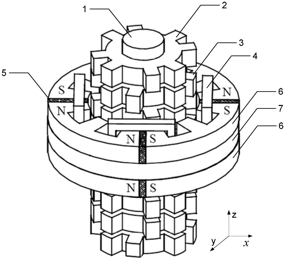
[0021] Specific implementation mode one: the following combination figure 1 Describe this embodiment, the cylindrical transverse magnetic field switch flux linkage permanent magnet linear motor described in this embodiment includes a mover and a stator; the mover is arranged inside the stator, and the mover moves linearly inside the stator along the axial direction; And there is a radial air gap between the mover and the stator;

[0022] The stator includes m short stator modules, and the m short stator modules are evenly distributed along the axial direction to form an m-phase motor; each short stator module includes p stator units and a plurality of stator magnetic isolation rings 7, between two adjacent stator units The axial space between them is provided with a stator magnetic isolation ring 7; each stator unit is formed by splicing 2n E-shaped structure iron cores 6 along the circumferential direction, and the inner arc surface of the E-shaped structure iron core 6 is pr...

specific Embodiment approach 2

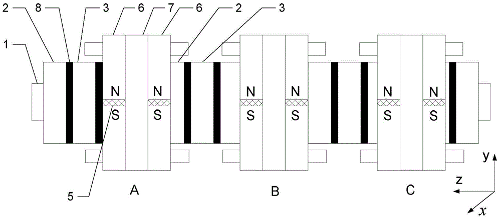
[0030] Specific implementation mode two: the following combination figure 2 Describe this embodiment. This embodiment will further explain Embodiment 1. The short stator modules of each phase are independent, and the distance d between two adjacent short stator modules is:

[0031] d=(2k+2 / m)τ p ;

[0032] Among them, τ p is the pole distance of the mover, and k is the reserved end winding space coefficient.

[0033] The axial direction is set as the z direction, and the plane where the first mover core 2 is located is the xoy plane. Arrange m sets of short stator modules in parallel along the axial direction, with a distance of (2k+2 / m)τ p , so that the electrical angle difference between two adjacent groups of short stator modules is 360 / m degrees to form an m-phase motor. figure 2 Given a motor p=2, m=3, two stator units are arranged in each group of short stator modules, a three-phase motor. Each phase is modularized and the magnetic circuit is independent, which fac...

specific Embodiment approach 3

[0034] Specific implementation mode three: the following combination figure 2 Describe this embodiment, this embodiment will further explain Embodiment 1, the axial thickness L of the first mover core 2 and the second mover core 3 r and the axial thickness L of the stator unit s equal.


PUM


Abstract

The invention discloses a cylindrical type transverse magnetic-field permanent-magnet flux-switching linear motor, belongs to the motor field, and aims to solve the problems of a relatively low space utilization rate, a complex manufacturing process, large permanent magnet dosage and high cost of an existing transverse magnetic-filed permanent-magnet motor. The cylindrical type transverse magnetic-field permanent-magnet flux-switching linear motor comprises a rotor and a stator, wherein the rotor is arranged inside the stator, and the rotor linearly moves inside the stator in the axial direction; a radial air gap is formed between the rotor and the stator; the stator comprises m short stator modules which are uniformly distributed in the axial direction to form an m-phase motor; each short stator module comprises p stator units and a plurality of stator magnetism isolating rings; the rotor comprises a shaft, w first rotor iron cores, w second rotor iron cores and a plurality of rotor magnetism isolating rings, and the structures of the first rotor iron cores and the second rotor iron cores are in mirror-image symmetry along the x axis or the y axis.

Description

technical field [0001] The invention relates to a modular permanent magnet motor and belongs to the field of motors. Background technique [0002] Traditional permanent magnet synchronous linear motors adopt an axial magnetic circuit structure, because the tooth slots are in the same plane, and the force density is relatively low, while the transverse magnetic field structure has the advantage of decoupling the electric load and the magnetic load, and the force density and power The density is higher than that of the permanent magnet linear motor with the traditional magnetic circuit structure, and it can maintain high efficiency and large torque especially at low speed. [0003] Although the traditional transverse magnetic field permanent magnet linear motor has high efficiency and torque density, there are problems such as complex structure, difficult processing and assembly, and low reliability; at the same time, short stators and long movers are used, and permanent magne...

Claims


Application Information

Patent Timeline
Patent Type & Authority Applications(China)
IPC IPC(8): H02K41/03
Inventor 郑萍朱少洪于斌张书宽刘家琦
Owner HARBIN INST OF TECH
Why Eureka
Try Eureka