
A drying device for a rotary screen printing machine

A drying device and printing machine technology, which is applied to printing machines, printing machines, general parts of printing machinery, etc., can solve the problems of ignoring the air circulation model, taking up a large space, and the temperature field of the fabric surface is disordered, so as to save the occupation of the drying room Space saving, space saving, high drying efficiency

Active Publication Date: 2017-08-25
ZHEJIANG JIAMING DYEING & FINISHING CO LTD
View PDF6 Cites 0 Cited by
  • Summary
  • Abstract
  • Description
  • Claims
  • Application Information

AI Technical Summary

Problems solved by technology

Temperature control is the most important for the drying function of the drying room. The temperature should not be too high or too low. If it is too high, it will easily brighten the color of the printing and dyeing, while the low temperature may not completely solidify the color paste.
[0005] The drying device of the existing rotary screen printing machine is to place the fabric flat, provide a heat source in the drying room and use a fan to diffuse the hot air to various positions in the room. This device ignores the air circulation model of the fabric drying environment. The temperature field on the surface of the fabric is disturbed, and the drying degree of the color paste is not good
At the same time, the printing speed of the rotary screen printing machine is 1.5-3 times faster than that of the flat screen printing machine, so the drying room must be lengthened to ensure that the fabric has enough time to dry, but the drying room is too long to take up a lot of space and the utilization rate is not high. it is necessary to improve

Method used


Image

  • A drying device for a rotary screen printing machine
  • A drying device for a rotary screen printing machine
  • A drying device for a rotary screen printing machine

Examples


Embodiment Construction

[0024] Below in conjunction with accompanying drawing and embodiment, the specific embodiment of the utility model is described in further detail. The following examples are used to illustrate the utility model, but not to limit the scope of the utility model.

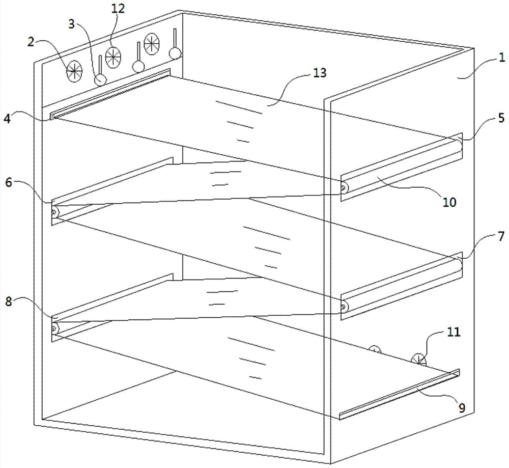
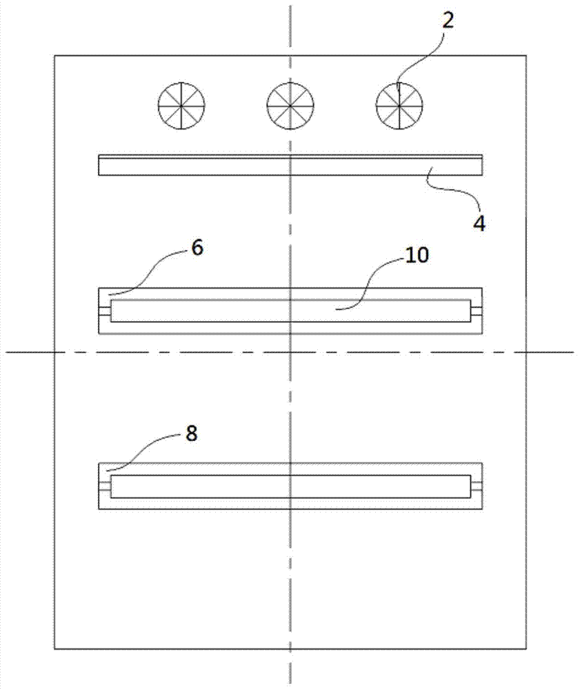
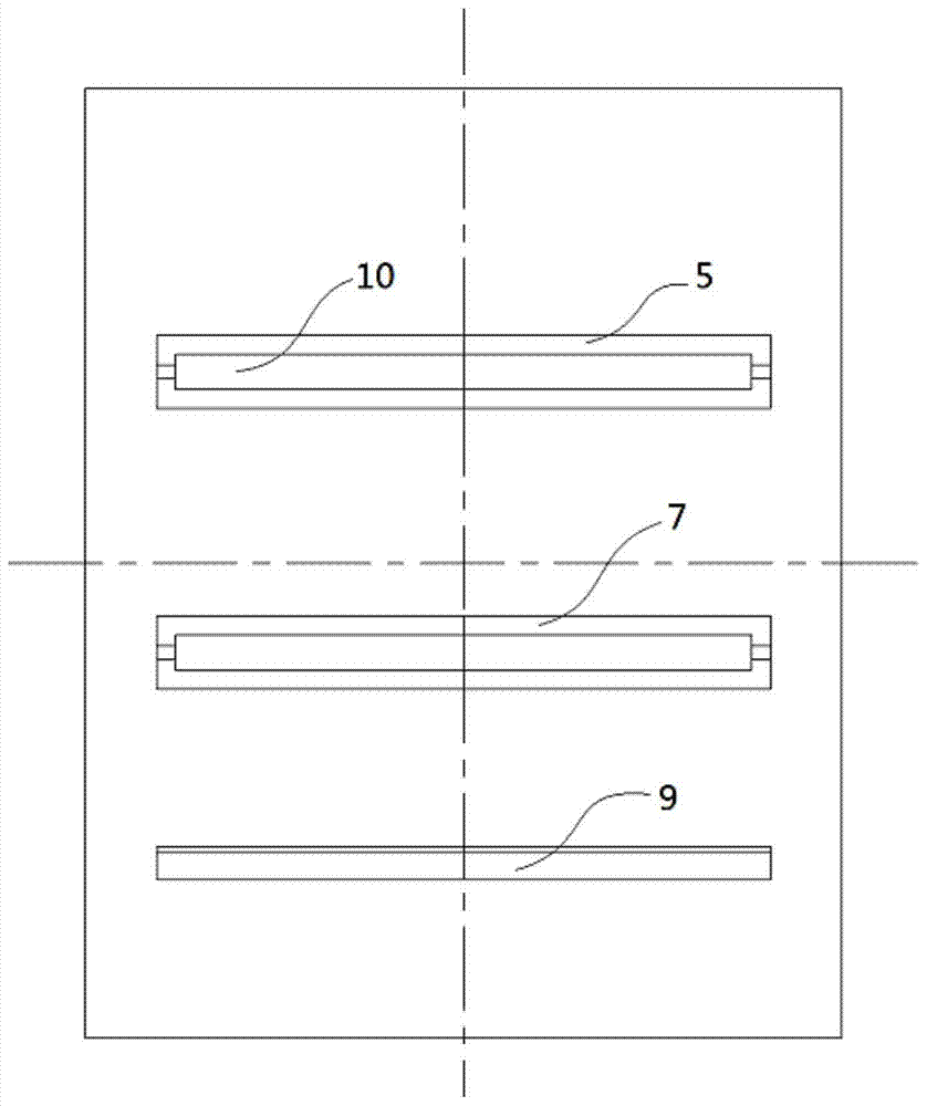
[0025] see Figure 1 to Figure 5 , the drying device for the rotary screen printing machine described in the utility model includes a drying room 1, the upper end of the drying room 1 is provided with a blower 2, and the front end of the blower 2 is provided with a heat source body 3; The drying room 1 is provided with a fabric inlet 4, a first air outlet 5 is provided on the drying room wall relative to the fabric inlet 4, and a second outlet is provided on the drying room wall relative to the first air outlet 5. The air outlet 6, the second air outlet 6 is provided with a third air outlet 7 on the wall plate of the drying room relative to the second air outlet 6, and the wall plate of the drying room 1 relative to t...


PUM


Abstract

The invention discloses a drying device for a rotary screen printing machine, which comprises a drying room, a blower is arranged at the upper end of the drying room, and a heat source body is arranged at the front end of the blower; a fabric inlet is arranged on the drying room below the blower, and a fabric inlet is arranged on the drying room below the blower. There is a first air outlet on the wall of the drying room opposite to the inlet, a second air outlet on the wall of the drying room opposite to the first air outlet, and a third air outlet on the wall of the drying room opposite to the second air outlet , the wallboard of the drying room opposite to the third air outlet is provided with a fourth air outlet, the wallboard of the drying room opposite to the first air outlet is provided with a fabric outlet, the first air outlet, the second air outlet, the third air outlet and Cloth guide rollers are arranged on the fourth air outlet; an exhaust fan is arranged at the lower end of the drying room. The invention provides a drying device for a rotary screen printing machine which saves the space occupied by a drying room, fully utilizes the space of the drying room, and greatly improves the drying efficiency of fabrics by utilizing the principle of indoor air circulation.

Description

[0001] Technical field: [0002] The utility model relates to the technical field of rotary screen printing machines, in particular to a drying device for rotary screen printing machines. [0003] Background technique: [0004] The drying room is the drying equipment of the rotary screen printing machine. After the fabric is printed and dyed by the rotary screen, the color paste on the fabric is still in a liquid or partially liquid-solid mixed state. The final product requires the color paste to be embedded in the surface of the fabric in a solid state. This requires the drying room to quickly solidify the color paste by means of high temperature and high pressure. Temperature control is the most important for the drying function of the drying room. The temperature should not be too high or too low. If it is too high, it will easily brighten the color of the printing and dyeing, while the low temperature may not completely solidify the color paste. [0005] The drying device ...

Claims


Application Information

Patent Timeline
Patent Type & Authority Patents(China)
IPC IPC(8): B41F23/04
Inventor 方碧娟林续贞林清芳
Owner ZHEJIANG JIAMING DYEING & FINISHING CO LTD
Learn More