Driving direction control method and control system after vehicle tire puncture

A driving direction and tire puncture technology, applied in the automotive field, can solve problems such as inability to solve direction loss, vehicle direction loss, tire puncture, etc., to solve the problem of deviation and direction loss, eliminate instantaneous vehicle steering, and ensure driving safety. Effect

Inactive Publication Date: 2015-08-05
朱炎炎
View PDF9 Cites 7 Cited by
  • Summary
  • Abstract
  • Description
  • Claims
  • Application Information

AI Technical Summary

Problems solved by technology

The result of the superposition of the above three factors will lead to a sharp decrease in the linear velocity of the wheel with a punctured tire, and a sharp increase in the linear velocity of the unexploded wheel on the other side, resulting in a sudden change in the linear velocity of the vehicle compared with that before the puncture and loss of balance
If the front wheel blows out, because the front wheel plays an important role in vehicle guidance, it will inevitably cause the vehicle to move to the side of the blown tire due to the huge difference in the linear speed of the wheels on both sides when the direction of the front wheel remains unchanged. Steering, causing the vehicle to lose control in an instant, causing serious traffic accidents
If the rear wheel blows out, the huge difference in the rolling speed of the tires on both sides of the blown tire will cause the vehicle to flick, which will also cause the vehicle to deviate from the correct driving direction and endanger the driving safety of the vehicle.
[0003] T

Method used


Image

  • Driving direction control method and control system after vehicle tire puncture
  • Driving direction control method and control system after vehicle tire puncture

Examples


Example Embodiment

[0023] The embodiments described below by referring to the figures are exemplary only for explaining the present invention and should not be construed as limiting the present invention.

[0024] In the description of the present invention, it should be noted that, unless otherwise specified and limited, the terms "installation", "connection", "connection" and so on should be interpreted in a broad sense, for example, it can be a mechanical connection or an electrical connection , may also be internal communication between two elements, may be a direct connection, or may be connected through an intermediary, and those skilled in the art may understand the above specific definitions according to specific situations.

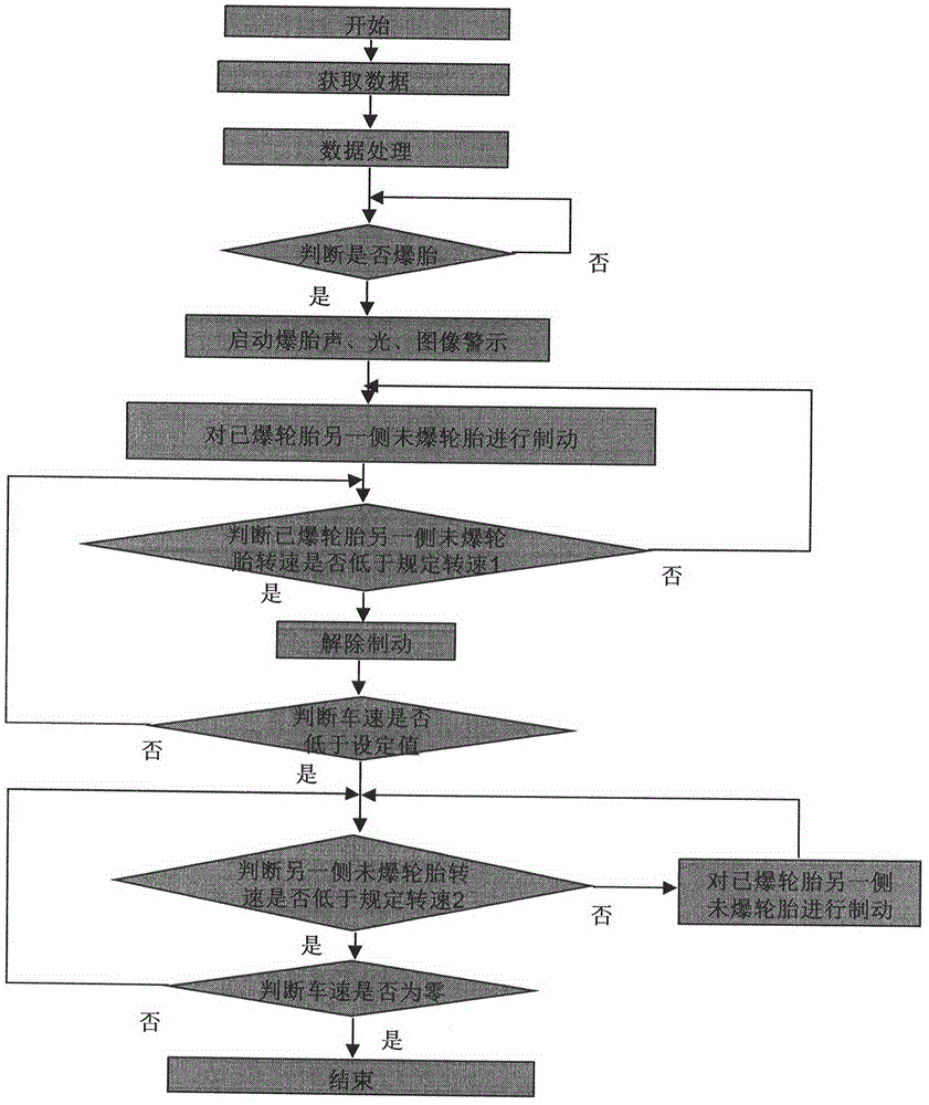
[0025] The method for controlling the driving direction of a vehicle after a tire blowout according to an embodiment of the present invention is described below with reference to the accompanying drawings.

[0026] as attached figure 1 As shown, it is a flowchart ...


PUM


Abstract

The invention proposes a driving direction control method and a control system after vehicle tire puncture. The control method comprises the steps of: obtaining the tire pressure information of each tire of a vehicle; obtaining the wheel rotating speed information; obtaining the steering wheel pointing information; obtaining the vehicle driving lane information; recording and analyzing the vehicle driving state and driving trajectory according to the obtained information; and immediately braking a non-punctured tire at the other side coaxial with a punctured tire if judging the vehicle has a flat tire, and reducing and controlling the rotating speed of the non-punctured tire at the other side coaxial with the punctured tire, so that the rotating speed of the coaxial non-punctured tire is kept in a safe and reasonable range compared with the rotating speed of the punctured tire. The method can enable the vehicle to timely eliminate the adverse effects generated by such factors as wheel diameter reduction and rolling resistance increment after the tire puncture, so that the vehicle is driven according to the planned trajectory, steering wheel pointing direction and lane trajectory to prevent the vehicle driving direction from being out of control suddenly after the tire puncture, and the tire puncture derived accidents are prevented.

Description

technical field [0001] The invention belongs to the technical field of automobiles, and relates to a method and a control system for controlling the driving direction of a vehicle after a tire blows out. Background technique [0002] During the running of the vehicle, the tire may blow out due to the road surface or the tire, causing the tire to lose air pressure instantly. After the tire loses air pressure, its impact on the driving of the vehicle: first, the effective driving radius of the wheel decreases instantaneously, and the rolling linear speed of the wheel decreases instantaneously when the rotation speed remains unchanged; second, the driving resistance of the wheel suddenly increases after the tire loses pressure and dries up. , leading to a further decrease in the rolling angular velocity and linear velocity of the tire; the third is that the vehicle adopts front-wheel drive, and the differential is equal-torque transmission. . The result of the superposition o...

Claims


Application Information

Patent Timeline
IPC IPC(8): B60T7/12B60Q9/00
CPCB60T7/12B60Q9/00
Inventor 朱炎炎
Owner 朱炎炎
Why Eureka
Try Eureka