Two-stage efficient atomization oil gun

A high-efficiency, oil gun technology, applied to lighting and heating equipment, burners, etc., can solve the problems of large maintenance, safety threats, fuel consumption, etc., and achieve the effect of low maintenance cost and high combustion efficiency

Active Publication Date: 2015-08-05
WUHAN QISI TECH
View PDF8 Cites 9 Cited by
  • Summary
  • Abstract
  • Description
  • Claims
  • Application Information

AI Technical Summary

Problems solved by technology

[0002] At present, the ignition oil guns widely used in power station boilers at home and abroad are simple mechanical atomization oil guns. This kind of oil gun is a relatively mature but backward oil gun. It has poor adaptability to oil types and can only burn light diesel oil. , and the combustion efficiency is not high in the cold state, the atomization particle size Sauter coefficient SMD≤200μm, the combustion efficiency can only reach 84%
Moreover, black smoke is emitted at the initial stage of ignition, which not only wastes fuel, but also pollutes the environment, and poses a huge threat to the safety of desulfurization and denitrification facilities. At the same time, this mechanical atomization oil gun also has the problems of large maintenance and high maintenance costs.

Method used


Image

  • Two-stage efficient atomization oil gun

Examples


Embodiment Construction

[0014] The present invention will be described in further detail below in conjunction with the accompanying drawings and embodiments, but these embodiments should not be construed as limiting the present invention.

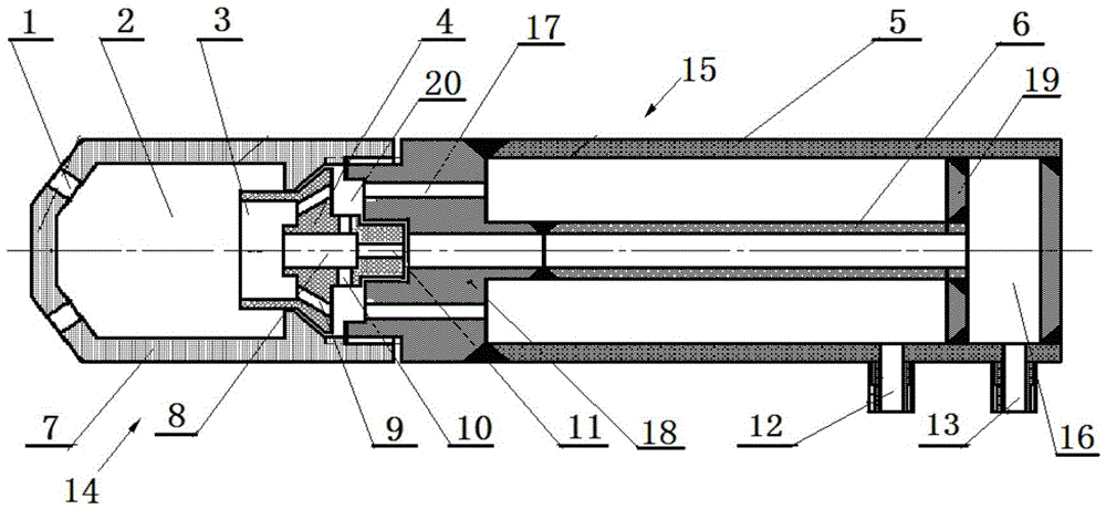
[0015] see figure 1 , the two-stage high-efficiency atomizing oil gun of the present invention includes a gun head 14 and a gun body 15, the gun head 14 is provided with a bubble chamber 2 and a nozzle 1 positioned at the head of the bubble chamber 2, and the gun body 15 is provided with a coaxial The inner tube 6 and the outer tube 5 that are set and isolated from each other, the head of the gun body 15 is provided with a connector 18 that communicates with the inner tube 6 and the outer tube 5 respectively, and the inner tube 6 and the outer tube 5 are connected with the inlet tube 5 respectively. The oil port 13 is connected to the atomizing gas inlet 12, and an oil-gas distributor 4 is arranged between the tail of the bubble chamber 2 and the head of the conne...


PUM


Abstract

The invention discloses a two-stage efficient atomization oil gun, wherein a gun head is provided with a bubble chamber and a nozzle; a gun body is provided with an inner tube and an outer tube; a connector respectively communicated with the inner tube and the outer tube is arranged at the head part of the gun body; the inner tube and the outer tube are respectively connected with an oil inlet and an atomization gas inlet; an oil gas distributor is arranged between the tail part of the bubble chamber and the head part of the connector, and is provided with an oil spray port, a vortex chamber and an energy gathering chamber coaxially connected in sequence; the oil spray port, the inner tube and the connector are formed to a fuel passage; radial gas inlets are uniformly distributed in the peripheral direction of the side wall of the tail part of the vortex chamber; gas feed holes are uniformly distributed in the peripheral direction of the middle part of the vortex chamber; an air separation cavity is encircled on the side wall of the tail part of the vortex chamber; annular inner cavities communicated with the outer tube and axial communicating holes communicated with the air separation cavity are uniformly distributed in the peripheral direction of the connector; the gas feed holes are communicated with an inner cavity of the energy gathering chamber and the air separation cavity; and the radial gas inlets are communicated with the vortex chamber and the air separation cavity. The two-stage efficient atomization oil gun has the characteristics of small oil particles, higher burning efficiency and more environmental protection, and can be applied to power station boilers.

Description

technical field [0001] The invention relates to a power station boiler, in particular to a two-stage high-efficiency atomizing oil gun. Background technique [0002] At present, the ignition oil guns widely used in power station boilers at home and abroad are simple mechanical atomization oil guns. This kind of oil gun is a relatively mature but backward oil gun. It has poor adaptability to oil types and can only burn light diesel oil. , and the combustion efficiency is not high in the cold state, the atomization particle size Sauter coefficient SMD≤200μm, the combustion efficiency can only reach 84%. Moreover, black smoke is emitted at the initial stage of ignition, which not only wastes fuel, but also pollutes the environment, and poses a huge threat to the safety of desulfurization and denitrification facilities. At the same time, this mechanical atomization oil gun also has the problems of large maintenance and high maintenance costs. . In recent years, the country has...

Claims


Application Information

Patent Timeline
Patent Type & Authority Applications(China)
IPC IPC(8): F23D11/04F23D11/10F23D11/36
CPCF23D11/04F23D11/10F23D11/36
Inventor 游必超王恒常敏李茂
Owner WUHAN QISI TECH
Why Eureka
Try Eureka