Bridge influence line dynamic test method

A dynamic test, influence line technology, applied in the direction of elasticity test, machine/structural component test, measuring device, etc., can solve the problem of not getting the ideal influence line characteristic curve, deviation, the existence of amplitude or shape distortion of the influence line, etc. question

Active Publication Date: 2015-08-05
CENT SOUTH UNIV
View PDF4 Cites 24 Cited by
  • Summary
  • Abstract
  • Description
  • Claims
  • Application Information

AI Technical Summary

Problems solved by technology

[0009] The present invention aims at problems such as amplitude or shape distortion of the obtained influence line in the existing bridge influence line dynamic testing method, which makes the test result deviate from the actual curve, and even cannot obtain the ideal characteristic curve of the influence line, etc., and provides a A new dynamic test method for real bridge influence lines to obtain high-precision and better reflect the actual bridge influence lines

Method used


Image

  • Bridge influence line dynamic test method
  • Bridge influence line dynamic test method
  • Bridge influence line dynamic test method

Examples


Embodiment 1

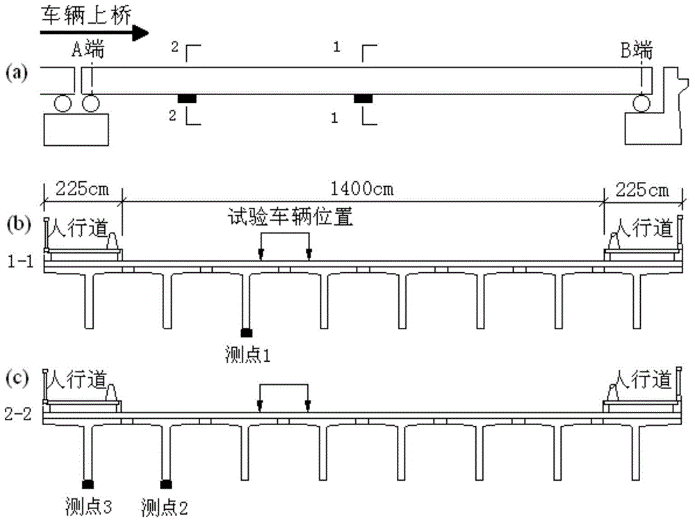
[0112] Taking a concrete simply supported T-beam bridge with a span of 20.0m as an example, the bridge strain influence line was tested on site and the auxiliary test showed that the vertical vibration frequency of the bridge was 3.06Hz. The direction and position of the vehicle crossing the bridge figure 1 (a), select section 1 at mid-span and section 2 at a distance of 3.1m from the end as the test section; there are 3 effective strain measuring points, and the measuring points are arranged as figure 1 (b), figure 1 As shown in (c), the 3rd beam from left to right at section 1 is measuring point 1, the 2nd beam from left to right at section 2 is measuring point 2, and the first from left to right at section 2 #Beam is measuring point 3. The section and measuring points are arranged as figure 1 Shown.

[0113] A three-axle vehicle is used as the test vehicle. The measured 1-2 wheelbase is 4.0m, the 2-3 wheelbase is 1.4m, and the measured three-axle weight is 8.94×10. 3 kg, 1...

Embodiment 2

[0121] From the perspective of model tests, the correct feasibility of the method for extracting the influence line of the bridge is verified and the advantages of similar methods are compared. The bridge model is a steel girder-slab bridge, which consists of two pieces of 100mm×68mm×4.5mm "I" steel beams and 4mm thick steel bridge deck welded together, with a length of 5.6m and a width of 0.56m. The vehicle model is a mass-adjustable 2-axle vehicle (wheelbase 0.365m). Its lateral position is constrained by the bridge deck rails. During the test, it is pulled by an electric motor and its speed is controlled. Appropriate approach bridges are installed in front of and behind the bridge to simulate the vehicle’s upper bridge and For bridge exit behavior, the strain measurement points are selected at the bottom of one side of the steel beam and arranged along the longitudinal direction. The model and measurement points are arranged as Image 6 , Measuring point 1 is arranged at 1 / 2 ...


PUM


Abstract

The invention relates to a bridge influence line dynamic test method, and belongs to the technical field of civil engineering application. A mixed function f(x)=f1(x)+f2(x) formed by a polynomial f1(x) and amplitude tunable sine wave f2(x) is established firstly, then response of a test point is tested by experiments, and dynamic response {re} of the test point under the effect of unit moving load is obtained by an anti-inference method; and finally least square fitting is performed on the obtained dynamic response {re} of the bridge crossing test point under the unit moving load by using the mixed function f(x), and a corresponding bridge influence line is separated and extracted. Difficulty of distortion of the obtained influence line in the aspect of amplitude or shape and the like in existing bridge influence line dynamic test methods can be solved by the method, and the bridge influence line which is high in precision and can further reflect reality is obtained.

Description

Technical field [0001] The invention relates to a method for dynamically testing bridge influence lines; it belongs to the technical field of civil engineering applications. Background technique [0002] The influence line of the bridge reflects the static characteristics of the bridge under the moving unit load. It is an important characteristic parameter similar to the frequency and the mode shape. It is necessary to test the influence line of the actual bridge structure in bridge inspection, monitoring, and evaluation. Compared with the static load test, the dynamic test method of the influence line based on the vehicle crossing test has the advantages of high test efficiency and large amount of test data. The process of the existing dynamic test method of influence line is generally: [0003] First, select a test point, and test the dynamic response of the point generated by the vehicle crossing the bridge; [0004] Then carry out the normalized backcalculation processing on th...

Claims


Application Information

Patent Timeline
Patent Type & Authority Applications(China)
IPC IPC(8): G01M5/00G06F19/00
Inventor 王宁波闫斌何立翔
Owner CENT SOUTH UNIV
Why Eureka
Try Eureka