Diamond anvil cell pressing machine trace gas liquefying plant
A technology of diamond-topping and trace gas, which is applied in the field of gas liquefaction equipment, can solve the problems of unsafety and consumption of a large amount of gas, and achieve the effect of improving the environment and eliminating hidden dangers of unsafety
- Summary
- Abstract
- Description
- Claims
- Application Information
AI Technical Summary
Problems solved by technology
Method used
Image
Examples
Embodiment 1
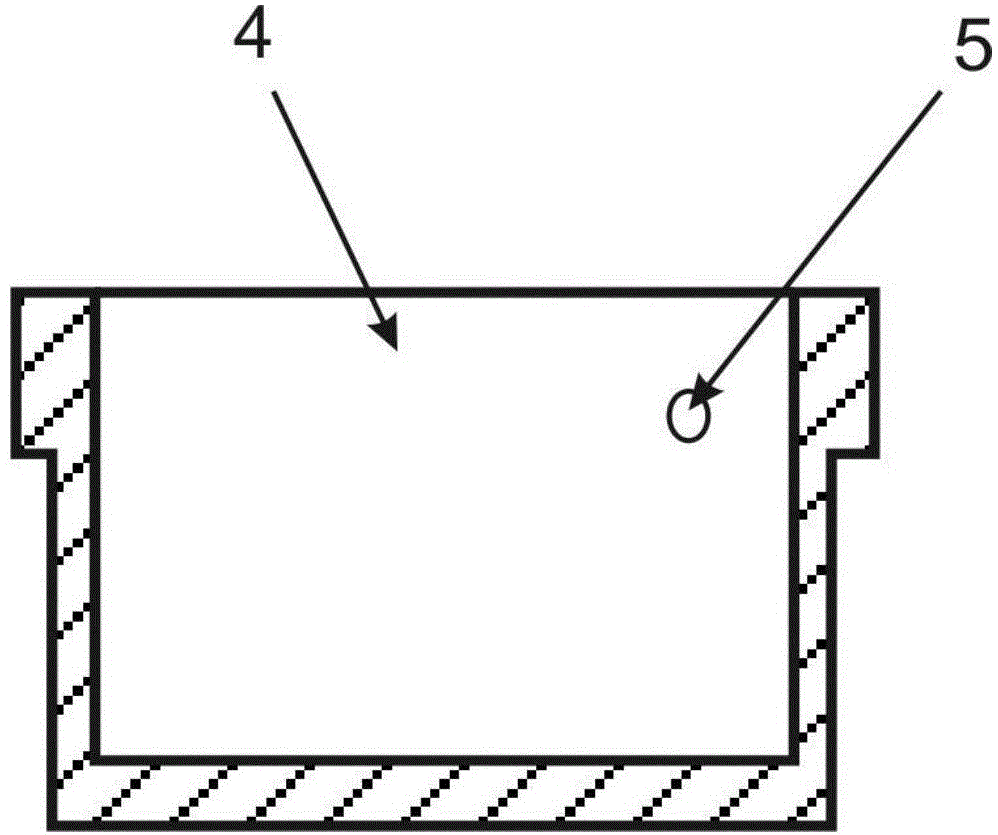
[0023] figure 2 A schematic cross-sectional view of the low temperature chamber 4 of the present invention is given. The cryogenic chamber can be in the shape of a cylinder, and the upper bottom surface is open for putting into the DAC press, and the upper end can be processed with protruding edges to prevent it from falling into the liquid nitrogen chamber 8 when it is put into the round hole in the middle of the upper cover 2 . The low temperature chamber 4 matches the overall appearance size and shape of the DAC compressor, so that the DAC compressor loaded therein can be cooled by liquid nitrogen faster. There is a gas inlet 5 on the edge protruding outwards, that is, the gas enters the passage of the diamond anvil sample cavity, the inner port of the gas inlet 5 can be docked with the observation hole on the side of the press, and the outer port of the gas inlet 5 can be connected with Gas cylinder 14 communicates.
[0024] image 3 A schematic cross-sectional view o...
Embodiment 2
[0027] Figure 5 The structure in which the liquid nitrogen circulation system and the low-temperature chamber of the diamond anvil press trace gas liquefaction device of the present invention are assembled together is given. Figure 5 Among them, 1 is the cavity jacket, 2 is the upper cover, 3 is the liquid nitrogen inlet, 4 is the cryogenic chamber, 5 is the gas inlet, 6 is the liquid nitrogen outlet, 7 is the cryogenic sealing ring, and 8 is the liquid nitrogen chamber.
[0028] Among them, the three parts outside the chamber 1, the upper cover 2 and the low temperature chamber 4 need to be tightly matched. The liquid nitrogen inlet 3 and the liquid nitrogen outlet 6 can be welded integrally with the upper cover by adopting stainless steel ferrule joints. A low-temperature sealing ring 7 can be installed between the cavity casing 1 and the upper cover 2, and the cavity casing 1 and the upper cover 2 are fixed and sealed by fastening bolts to prevent liquid nitrogen from se...
Embodiment 3
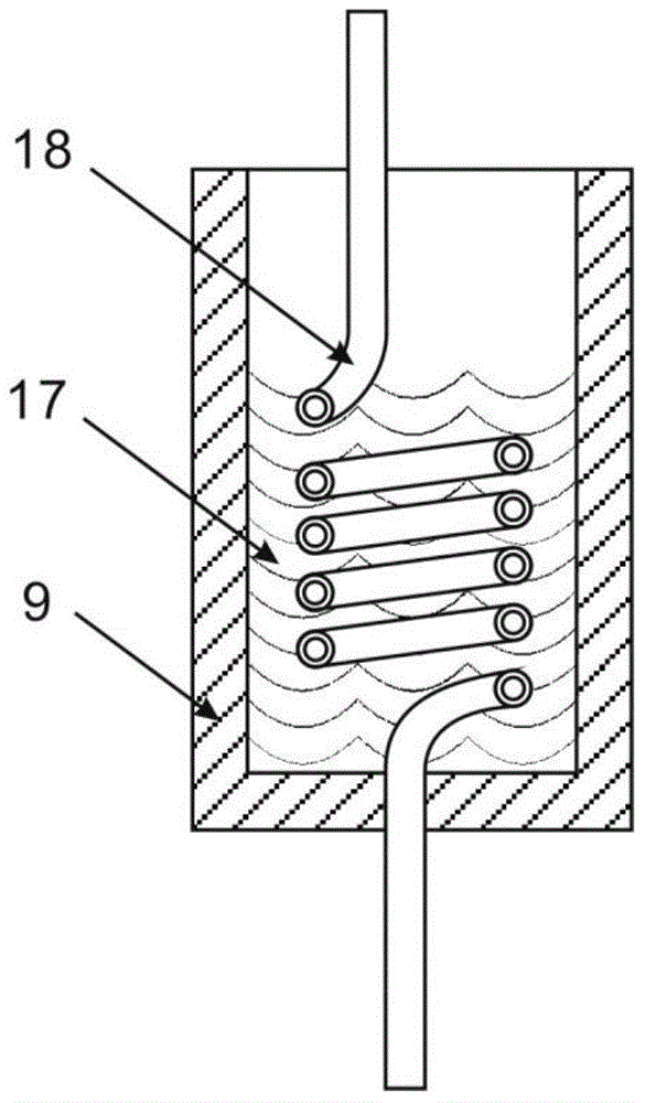
[0030] Figure 6 An overall structure diagram of the present invention is provided, Figure 6 Among them, 9 is a liquid nitrogen barrel, 10 is a liquid nitrogen injection pipe, 11 is a gas volume control valve, 12 is a gas injection pipe, 13 is a pressure reducing valve, 14 is a gas cylinder, 15 is a nitrogen exhaust control valve, and 16 is a nitrogen exhaust pipe .
[0031] Will Figure 5 The cavity part of the liquid nitrogen circulation system shown is connected as a whole through the liquid nitrogen barrel 9, the liquid nitrogen injection pipe 10, the nitrogen gas removal control valve 15 and the nitrogen gas removal pipe 16 to form the liquid nitrogen circulation system of the present invention. Pour liquid nitrogen into the liquid nitrogen barrel 9, and cool down the cryogenic chamber 4 and the diamond anvil press through this circulation system.
[0032] Figure 6 The gas volume control valve 11 in it, the gas injection pipe 12, the liquefied gas path formed by the...
PUM
 Abstract
Description
Claims
Application Information
 - R&D
- Intellectual Property
- Life Sciences
- Materials
- Tech Scout
- Unparalleled Data Quality
- Higher Quality Content
- 60% Fewer Hallucinations
Browse by: Latest US Patents, China's latest patents, Technical Efficacy Thesaurus, Application Domain, Technology Topic, Popular Technical Reports.
© 2025 PatSnap. All rights reserved.Legal|Privacy policy|Modern Slavery Act Transparency Statement|Sitemap|About US| Contact US: help@patsnap.com


