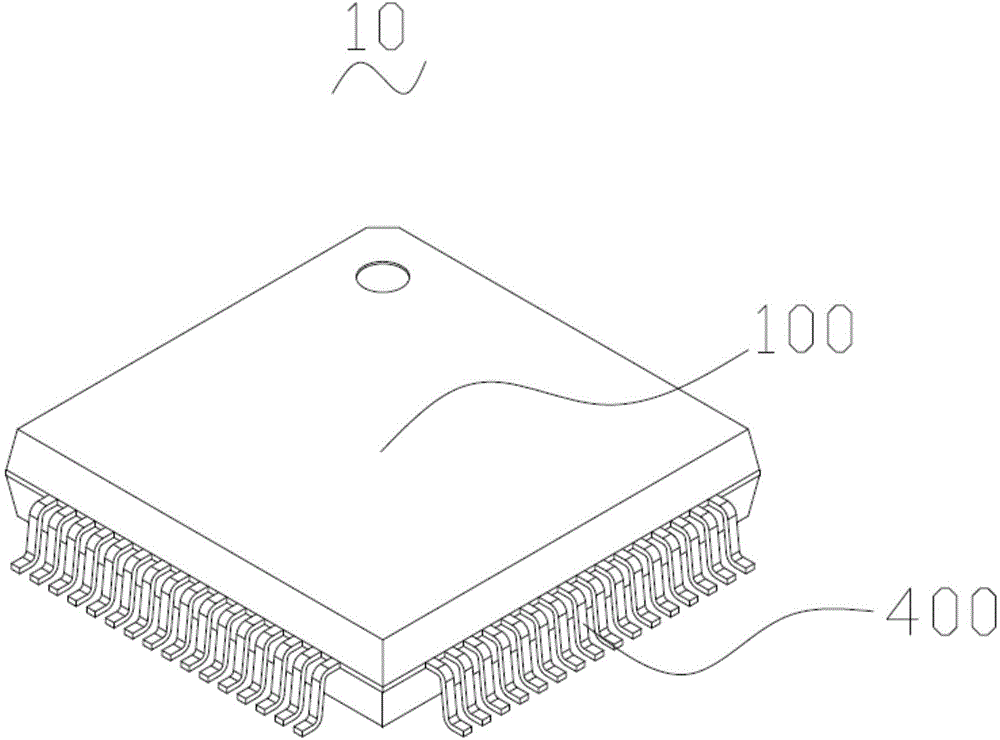
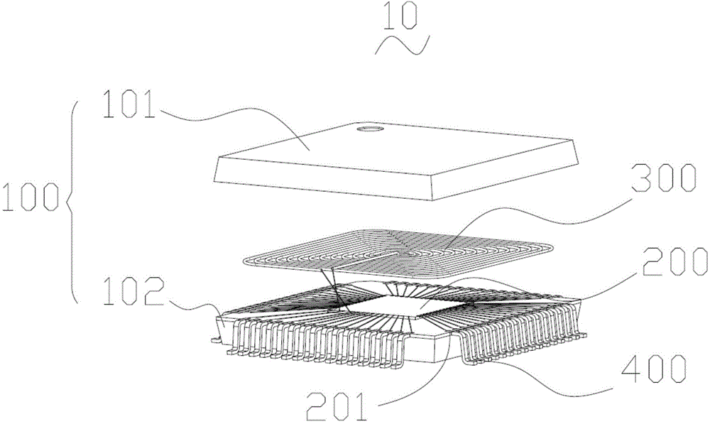
Wireless charging device

A wireless charging and coil technology, applied in circuit devices, battery circuit devices, current collectors, etc., can solve the problems of large volume, low production cost, complex structure, etc.

Active Publication Date: 2015-08-05
SHENZHEN TITAN MICRO ELECTRONICS
View PDF4 Cites 2 Cited by
  • Summary
  • Abstract
  • Description
  • Claims
  • Application Information

AI Technical Summary

Problems solved by technology

[0003] Based on this, it is necessary to provide a wireless charging device with high integration, simple structure and small size for the existing wireless charging devices with large volume, complex structure, complicated manufacturing process and high failure rate. Features of low cost

Method used


Image

  • Wireless charging device
  • Wireless charging device

Examples


Embodiment Construction

[0015] In order to facilitate the understanding of the present invention, the present invention will be described more fully below with reference to the associated drawings. Preferred embodiments of the invention are shown in the accompanying drawings. However, the present invention can be embodied in many different forms and is not limited to the embodiments described herein. On the contrary, the purpose of providing these embodiments is to make the disclosure of the present invention more thorough and comprehensive.

[0016] It should be noted that when an element is referred to as being “disposed on” another element, it may be directly on the other element or there may also be an intervening element. When an element is referred to as being "connected to" another element, it can be directly connected to the other element or intervening elements may also be present. The terms "vertical," "horizontal," "left," "right," and similar expressions are used herein for purposes of ...


PUM


Abstract

The invention relates to a wireless charging device, including a packaging shell, a coil and a control circuit. The coil is electrically connected with the control circuit, the coil and the control circuit are packaged in the packaging shell, the control circuit is integrated on a wafer, and the wafer is packaged in the packaging shell. Through integral packaging, the wireless charging device has the characteristics of high integration, simple structure and small volume, the failure rate of the packaged wireless charging device is greatly reduced in a working process, machining of the control circuit is facilitated, and production cost is reduced.

Description

technical field [0001] The invention relates to the field of wireless charging, in particular to a wireless charging device. Background technique [0002] At present, smart devices such as handheld devices and wearable devices are widely used. In order to meet the needs, these smart devices tend to become thinner and smaller. Therefore, these devices need to be highly integrated. More electronic components are integrated in the space to achieve more functions. With the convenience and humanization of the application of these smart devices, smart devices have gradually added wireless charging functions. Traditional wireless charging uses the separation of inductors and control circuits. design, in which the charging control circuit is composed of PCB (Printed Circuit Board), IC (Integrated Circuit Integrated Circuit), and passive components such as resistors and capacitors. The control circuit is bulky, with various manufacturing processes and complex structures. , prone to ...

Claims


Application Information

Patent Timeline
Patent Type & Authority Applications(China)
IPC IPC(8): H02J7/02
Inventor 张卫黄伯明张伟彭良宝门洪达
Owner SHENZHEN TITAN MICRO ELECTRONICS
Why Eureka
Try Eureka