
Method for operating recuperation brake of motor vehicle and recuperation brake

A technology for motor vehicles and brakes, which is applied in the field of regenerative brakes and regenerative brakes for running motor vehicles, can solve problems such as reduced driving stability, and achieve the effects of improving efficiency, increasing complexity, and optimizing efficiency.

Active Publication Date: 2015-08-05
CONTINENTAL AUTOMOTIVE GMBH
View PDF6 Cites 8 Cited by
  • Summary
  • Abstract
  • Description
  • Claims
  • Application Information

AI Technical Summary

Problems solved by technology

Furthermore, it is desirable that the operation of the regenerative brake not lead to a reduction in driving stability despite the use of a system which allows for a higher efficiency

Method used


Image

  • Method for operating recuperation brake of motor vehicle and recuperation brake
  • Method for operating recuperation brake of motor vehicle and recuperation brake

Examples


Embodiment Construction

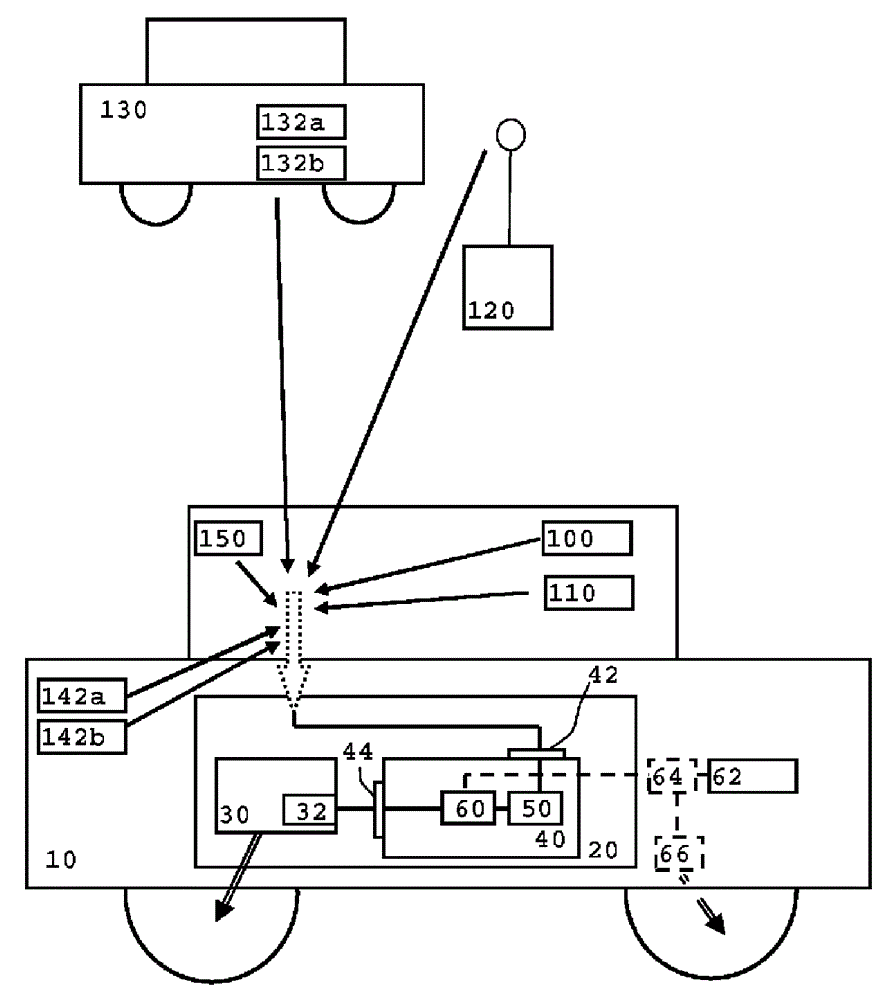
[0042] figure 1 A motor vehicle as described here is shown schematically together with a regenerative brake as also described here. also, figure 1 Other sources of information are shown and used to explain the methods described herein.

[0043] The motor vehicle 10 includes a regenerative brake 20 with an electric motor 30 including a control unit 32 for the electric motor 30 . Regenerative brake 20 also includes a control device 40 with an interface 42 serving as an input interface for at least one input, as described here. Basically, a motor vehicle may comprise several electric machines, for example one electric machine per axle or per wheel. According to the present invention, the regenerative brake includes all or part of the motor. Furthermore, only one electric motor is used for the description of the figures for the sake of simplicity of illustration, wherein instead, as noted, a plurality of electric motors can also be provided. The electric motor used here can t...


PUM


Abstract

A method for operating a recuperation brake (20) of a motor vehicle (10) is described. Firstly, a future operating intensity of the recuperation brake (20) is estimated for a section of route to be travelled on by the motor vehicle (10) on the basis of an input which characterizes the driving style of the section of route to be travelled on. In addition, a maximum slip-free vehicle braking power for the section of route is estimated as a function of the input. In addition, the braking power of the recuperation brake (20) is set to a setpoint braking power which is not greater than the maximum vehicle braking power for the section of route, and finally the recuperation brake (20) is activated on the section of route to be travelled on with the setpoint braking power. In addition, a recuperation brake for carrying out the method is described.

Description

Background technique [0001] Regenerative brakes are used in vehicles to convert the kinetic energy of the vehicle into electrical energy that can be temporarily stored. In this way, the energy that occurs during braking can be reused in contrast to the non-reusable braking energy of conventional friction brakes. [0002] In particular in the case of electric vehicles and hybrid vehicles, the efficiency of the energy required for the operation of the vehicle can thus be increased. The motor vehicles described here have two, four or more wheels. These wheels can be distributed on 1, 2 or more axles. [0003] Laid-open document DE 10 2010 041 544 A1 describes a driver assistance system for consumption-controlled driving, in which route data of the driving route ahead are evaluated. A slowdown indicator (Verzägerungsanweisung) is displayed to the driver if a situation occurs ahead in which a lower speed would be expected. As a further consequence, the operating strategy, in pa...

Claims


Application Information

Patent Timeline
IPC IPC(8): B60L11/16B60L3/10B60L7/14B60L7/18B60L7/26B60L15/20B60L7/22B60W10/08B60W30/18B60W50/00B60W20/00G08G1/16B60L50/30
CPCB60L2240/423G08G1/166Y02T10/7291B60L2250/18G08G1/162B60W2550/408B60L2240/622B60L3/10Y02T10/7283B60L7/18Y02T90/162G08G1/163B60L2260/44B60W2550/142B60L2240/62B60L2240/68B60L7/22B60L2240/662Y02T90/16B60L2260/54B60W2550/308Y02T10/84B60W2550/12B60W50/0097B60L7/14B60L2240/647B60L2240/645B60L2240/642B60W2550/143B60L2240/70B60W30/18127B60W2550/402B60L2260/50B60L15/2045B60L15/2009Y02T10/642B60W10/08B60L2260/28B60W2550/146B60W2552/15B60W2552/20B60W2552/30B60W2554/801B60W2555/20B60W2556/50B60W2556/65Y02T10/64Y02T10/70Y02T10/72B60T8/172B60T8/24
Inventor J.M.迈特特M.韦格雷尔
Owner CONTINENTAL AUTOMOTIVE GMBH
Features
  • Generate Ideas
  • Intellectual Property
  • Life Sciences
  • Materials
  • Tech Scout
  • Unparalleled Data Quality
  • Higher Quality Content
  • 60% Fewer Hallucinations
Learn More