Supercharge Your Innovation With Domain-Expert AI Agents!

Temperature Sensor

A temperature sensor and sensor technology, which is applied to thermometers, resistors with negative temperature coefficients, and parts of thermometers, etc., can solve the problems of damage measurement objects, large volume of thermal sensitive elements, and difficult temperature detection, etc., to achieve accurate Effect of measurement temperature, good B constant, and high heat resistance

Active Publication Date: 2017-04-05
MITSUBISHI MATERIALS CORP
View PDF8 Cites 0 Cited by
  • Summary
  • Abstract
  • Description
  • Claims
  • Application Information

AI Technical Summary

Problems solved by technology

[0011] That is, in the technology described in Patent Document 1, although a spherical thermistor or the like is used as the thermal element, in this case, since it is spherical or elliptical about 1 mm in shape, it makes point contact with the heating roller, Difficult to perform accurate temperature detection
Also, the thermal sensor has a large volume, so there is a bad situation of poor responsiveness
Also, there is a risk of damage to the rotating roller surface due to point contact
[0012] In addition, in the technology described in Patent Document 2, since a thin film thermistor is used as the thermal element, it can be in surface contact with the heating roller, but if it includes an insulating substrate and a lead part constituting the thin film thermistor, it still has a bulky , so there is a problem of poor responsiveness
[0013] Furthermore, in the technology described in Patent Document 3, in order to bring the metal contact plate into contact with the measurement object, the measurement object may be damaged, and the volume (thickness, etc.) of the thermocouple and the contact plate, and the heat generated by the metal contact plate released, but there is a problem of poor responsiveness

Method used


Image

  • Temperature Sensor
  • Temperature Sensor
  • Temperature Sensor

Examples


Embodiment

[0102] Next, for the temperature sensor involved in the present invention, refer to Figures 10 to 18 , the results of the evaluation by the examples prepared according to the above-mentioned embodiments will be described in detail.

[0103]

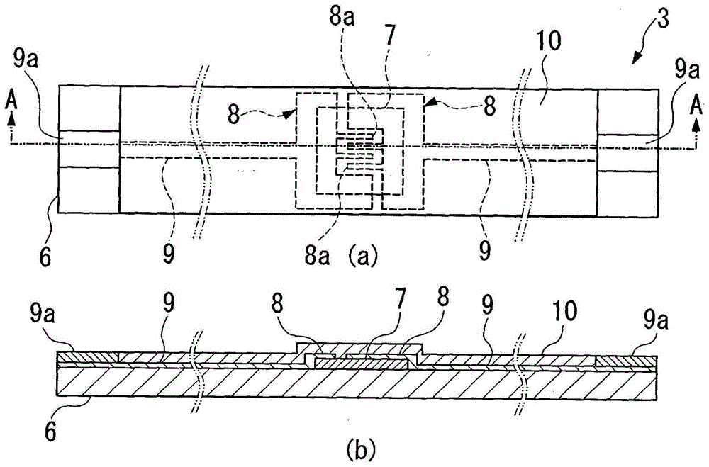
[0104] Examples and comparative examples for evaluating the thermistor material layer (thin film thermistor portion 7 ) of the present invention were prepared as follows Figure 10 The element 121 for film evaluation is shown.

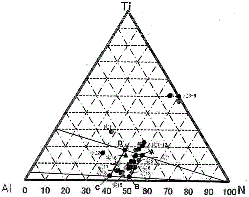
[0105] First, by the reactive sputtering method, using Ti—Al alloy targets of various composition ratios, on the Si wafer with thermal oxide film to serve as the Si substrate S, at various composition ratios shown in Table 1, a thickness of Thin-film thermistor portion 7 of 500 nm metal nitride material. The sputtering conditions at this time were as follows: reaching vacuum degree: 5×10 -6 Pa, sputtering gas pressure: 0.1 to 1 Pa, target input power (output): 100 to 500 W, and produced by changing the nitro...


PUM

PropertyMeasurementUnit
thicknessaaaaaaaaaa
thicknessaaaaaaaaaa
thicknessaaaaaaaaaa

Abstract

The present invention provides a temperature sensor comprising: a pair of lead frames; a sensor part connected to the pair of lead frames; The resistance part is pattern-formed in the central part of the surface of the insulating film; a pair of comb-shaped electrodes has a plurality of comb-teeth parts above the thin-film thermistor part and is pattern-formed opposite to each other; and a pair of pattern electrodes, One end is connected to a pair of comb-shaped electrodes, and the other end is connected to a pair of lead frames at the end of the insulating film, and the surface of the insulating film is patterned, and the insulating film is bent into a roughly U-shaped state. The thin film thermistor part is arranged at the tip part, and both ends are fixed to a pair of lead frames.

Description

technical field [0001] The present invention relates to a temperature sensor suitable for measuring the temperature of a heating roller of a copier, a printer, or the like. Background technique [0002] Generally, in a heat roller used in a copier or a printer, in order to measure the temperature, a temperature sensor is provided in a contact state. As such a temperature sensor, for example, Patent Documents 1 and 2 propose a temperature sensor including: a pair of lead frames; a thermal element arranged and connected between the lead frames; and a holding portion formed on the pair of lead frames the end of the frame; and the film sheet, which is arranged on one side of the lead frame and the heat-sensitive element and is in contact with the heating roller. [0003] This temperature sensor uses the elastic force of the lead frame to contact the surface of the heating roller, thereby performing temperature detection. [0004] In addition, in the above-mentioned Patent Docu...

Claims


Application Information

Patent Timeline
Patent Type & Authority Patents(China)
IPC IPC(8): G01K7/22G01K13/08H01C7/04
CPCG01K13/08H01C7/04G01K1/143H01C7/006H01C7/008H01L2924/0002H01C1/142H01C1/14H01C1/1406H01C1/1413G01K7/22H10N10/80H01L2924/00H01L23/495
Inventor 长友宪昭稻叶均竹岛一太田中宽
Owner MITSUBISHI MATERIALS CORP
Features
  • R&D
  • Intellectual Property
  • Life Sciences
  • Materials
  • Tech Scout
  • Unparalleled Data Quality
  • Higher Quality Content
  • 60% Fewer Hallucinations
Learn More