

Third axis group structure on numerical control repeated cutting material moving type lathe
A kind of technology of walking machine and shaft group, which is applied in the direction of metal processing machinery parts, metal processing, metal processing equipment, etc., can solve problems such as the inability to realize complex parts, and achieve the effect of avoiding resistance, reducing heat generation, and improving its own accuracy.
- Summary
- Abstract
- Description
- Claims
- Application Information
AI Technical Summary
Problems solved by technology
Method used
Image

Examples
Embodiment 1
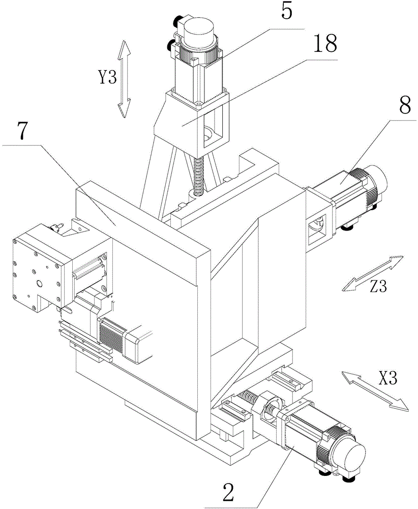
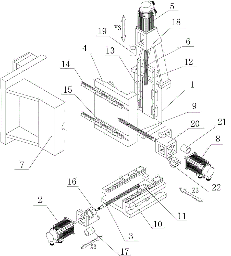
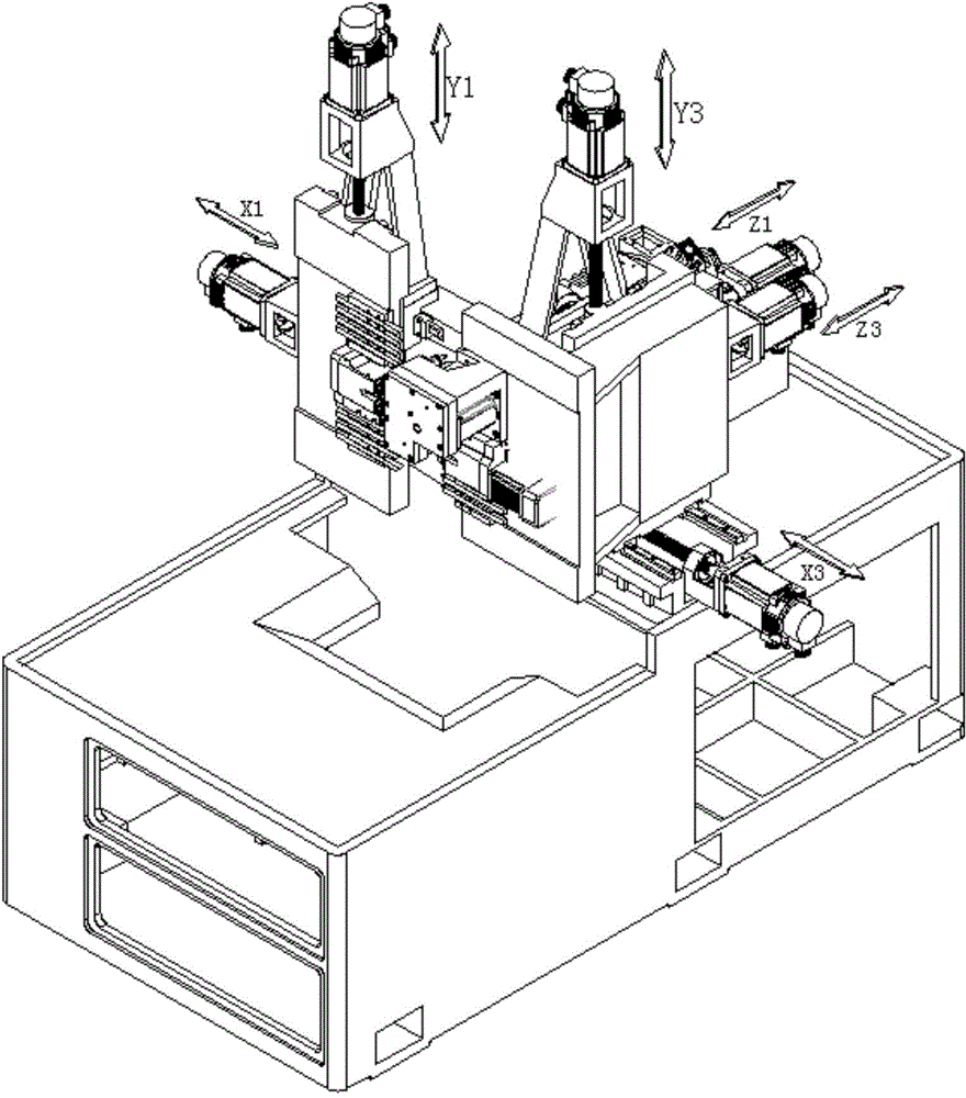
[0044] like figure 1 and figure 2 The third axis group used in turning and milling machine tools includes a bed, X3 axis group, Y3 axis group and Z3 axis group arranged on the bed.
[0045] The X3-axis group includes an L-shaped X3-axis slide plate 1, an X3-axis motor 2, an X3-axis screw rod 3, an X3-axis rail 10, an X3-axis slider 11, and an X3-axis motor seat 16 for installing the X3-axis motor 2 , X3-axis coupling 17 and X3-axis seat 22, the X3-axis slide plate 1 includes a first X3-axis slide plate parallel to the XZ plane and a second X3-axis slide plate parallel to the YZ plane. The X3-axis rail 10 is arranged on the machine bed, and the X3-axis slider 11 is arranged on the first X3-axis slide plate, and the X3-axis rail 10 and the X3-axis slider 11 form a sliding pair. The bottom of the first X3-axis slide plate is also provided with an X3-axis nut, and the X3-axis screw rod 3 cooperates with the X3-axis nut to form a thread pair. The X3 axis motor base 16 is arrang...
Embodiment 2
[0051] The structure of this embodiment is substantially the same as that of Embodiment 1, the difference is that the X3-axis slide plate 1 is provided with an X3-axis threaded blind hole (not shown in the figure), and one end of the X3-axis screw rod 3 Extend into the X3 axis threaded blind hole and be threadedly connected with the X3 axis threaded blind hole; the Y3 axis slide plate 4 has a Y3 axis threaded blind hole (not shown in the figure), and the Y3 axis screw rod 6 One end extends into the Y3-axis threaded blind hole and is threadedly connected with the Y3-axis threaded blind hole; the Z3-axis slide plate 7 has a Z3-axis threaded blind hole (not shown), and the Z3-axis screw rod 9 One end stretches into the Z3 axis threaded blind hole and is threadedly connected with the Z3 axis threaded blind hole.
[0052] Some equivalent improvements can be made in this embodiment, such as X3-axis threaded blind holes, Z3-axis threaded blind holes and Y3-axis threaded blind holes a...
Embodiment 3
[0054] The difference between this embodiment and Embodiment 1 is that the tool mounting seat 7 is a turret, and the Z3 axis rail that forms a sliding pair with the Z3-axis slider 15 is installed on the turret, and the tool is installed on the turret, and the 360-degree rotation of the turret is used. To realize tool change, the rest of the structure is the same as that of Embodiment 1, and will not be repeated here. At this time, the turret rotates 360°, and the tools at each station of the turret can be changed flexibly to realize the processing of the workpiece. This assembly structure not only saves space, but also can be installed on the turret. Increase the variety and quantity of cutting tools, power heads, etc. to a certain extent, and the disc design is conducive to chip removal when the tool is processing parts, and to a greater extent strengthens the rigidity of the tool when processing parts. Such a structure increases the practical operability of the machine tool ...
PUM
 Abstract
Description
Claims
Application Information