
General chassis steering gear

A technology of steering gear and chassis, which is applied in steering mechanism, non-deflectable wheel steering, transportation and packaging, etc. It can solve the problems of difficult processing, high equipment cost, complicated control, etc., and achieves simple structure, flexible steering and wide application Effect

Active Publication Date: 2015-08-12
ROBOT TIME BEIJING TECH CO LTD
View PDF6 Cites 0 Cited by
  • Summary
  • Abstract
  • Description
  • Claims
  • Application Information

AI Technical Summary

Problems solved by technology

[0003] The chassis of existing robots is generally controlled by dual motors, which can independently rotate the straight line or turn of the solid-line chassis, making it difficult to control the trajectory
The two driving wheels are separately controlled by two motors. The problem is that the control of the robot is relatively complicated when it moves forward in a straight line. high cost
At the same time, there is a problem that the power required by the robot to move and turn is not the same, but the motor with the same power is used, the cost is lost, and the difficulty of control is relatively increased.
[0004] The steering gear of existing tanks is not flexible enough, difficult to process and easy to damage

Method used


Image

  • General chassis steering gear
  • General chassis steering gear
  • General chassis steering gear

Examples


Embodiment 1

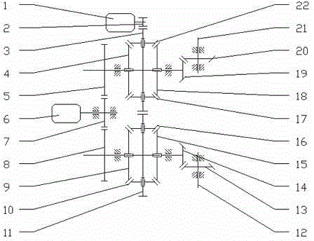
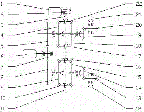
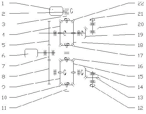
[0031] like figure 1 As shown, the universal chassis steering gear of the present invention includes a front and rear drive motor 1 and a steering drive motor 6. The front and rear drive motors 1 drive the first differential planet carrier gear 3 through the front and rear input gears 2, and the first differential A first differential first planetary bevel gear 22 and a first differential second planetary bevel gear 17 are fixed axially and vertically on the carrier gear 3 of the first differential, the first differential first planetary bevel gear 22 and The first differential gear and the second planetary bevel gear 17 are jointly meshed with the first differential gear input bevel gear 4 on one side, and the first differential gear first output bevel gear 18 on the other side. The input bevel gear 4 of the first differential rotates coaxially with the first output bevel gear 18 of the first differential; the first output bevel gear 18 of the first differential is coaxially ...

Embodiment 2

[0038] like Figure 7As shown, the basic structure and principle of this embodiment is the same as that of Embodiment 1, the difference is that the steering drive motor 6 is connected to the first differential carrier gear 3 and the second differential carrier gear respectively through the steering input gear 7 11 meshing; the front and rear drive motors 1 drive the first differential input gear 5 through the front and rear input gears 2, and the first differential input gear 5 meshes with the second differential input gear 8.

Embodiment 3

[0040] like Figure 8 As shown, the basic structure and principle of this embodiment is the same as that of Embodiment 1, the difference is that the front and rear drive motors 1 drive the second differential carrier gear 11 through the front and rear input gears 2, and the second differential carrier gear 11 Meshes with the first differential carrier gear 3; the steering drive motor 6 drives the second differential input gear 8 through the steering input gear 7, and the second differential input gear 8 drives the first differential through the transition gear 23 input gear 5.

[0041] In addition, if Figure 9 , 10 As shown, the first differential planetary bevel gear and the second differential planetary bevel gear can be expanded from two to three or four or more.


PUM


Abstract

The invention provides a general chassis steering gear for achieving coaxial bilateral rotation in the same direction or opposite directions. The general chassis steering gear comprises a front-back drive motor and a steering drive motor which act on a first output shaft and a second output shaft through a first differential mechanism and a second differential mechanism respectively. One motor is responsible for front-back movement of a robot, the other motor achieve left-right steering control of the robot, and the general chassis steering gear has the full-path coverage capacity of pivot steering and running steering. The general chassis steering gear is simple in structure, low in cost, easy to machine, easy to control, flexible in steering and wide in application.

Description

technical field [0001] The invention relates to a traveling equipment, in particular to a universal chassis steering gear. Background technique [0002] Chassis steering gears are generally used for driving and steering of tracked chassis such as tanks, and are now widely used in chassis such as vehicles and robots. However, in the past technology, the change of the left and right wheel speed ratios was realized by the planetary gear shifting with different kneading methods of the clutch, so the requirements for the clutch components were relatively high. In recent years, the steering of tanks has begun to use more and more hydraulically driven methods to achieve steering. [0003] The chassis of the existing robot is generally controlled by two motors, which independently rotate the solid-line chassis to go straight or turn, and the motion trajectory is difficult to control. The two driving wheels are separately controlled by two motors. The problem is that the control ...

Claims


Application Information

Patent Timeline
Patent Type & Authority Applications(China)
IPC IPC(8): B62D11/02
Inventor 郑世杰
Owner ROBOT TIME BEIJING TECH CO LTD
Learn More