Buoyancy ball ejection device for underwater carrier

A technology of underwater vehicles and ejection devices, applied in transportation and packaging, underwater operation equipment, ships, etc., can solve problems affecting performance, loss, impact of vehicles, etc., and achieve the goal of improving use efficiency and reducing sealing requirements Effect

Active Publication Date: 2015-08-12
HARBIN ENG UNIV
View PDF7 Cites 9 Cited by
  • Summary
  • Abstract
  • Description
  • Claims
  • Application Information

AI Technical Summary

Problems solved by technology

[0002] After the underwater operation equipment such as the autonomous underwater robot completes the operation in the complex ocean environment, it needs to surface for recovery for the next use.

Method used


Image

  • Buoyancy ball ejection device for underwater carrier
  • Buoyancy ball ejection device for underwater carrier
  • Buoyancy ball ejection device for underwater carrier

Examples


Embodiment Construction

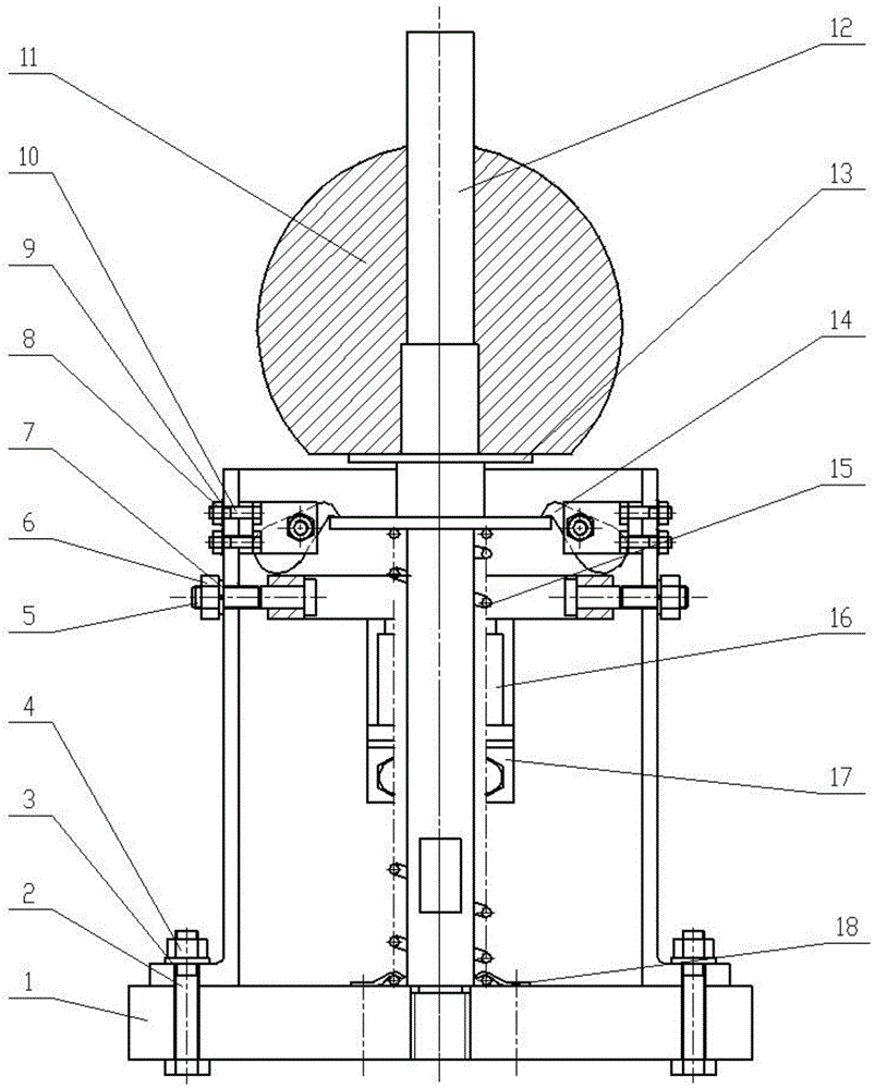
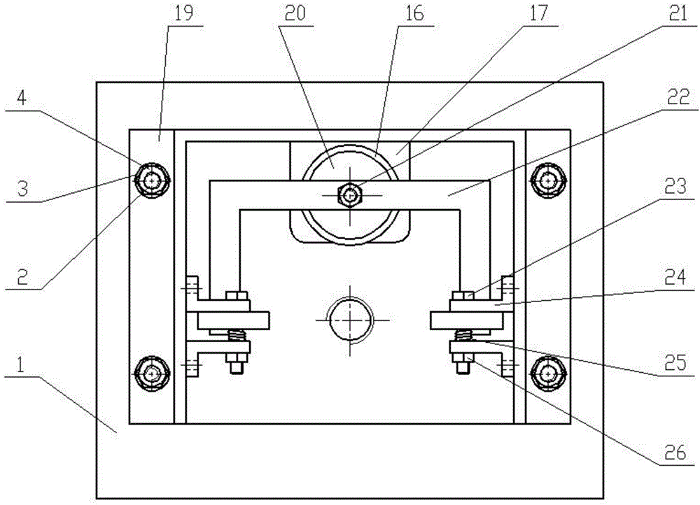
[0017] The present invention is described in more detail below in conjunction with accompanying drawing example:

[0018] combine Figure 1~5 , the present invention mainly is made up of buoyancy ball positioning part, lever conversion part, buoyancy ball release part. The buoyancy ball spheroid 11 is installed on the spheroid support 13, and through hole is arranged in the middle of the spheroid support 13, is enclosed within on the guide bar 12. The lower end of the guide rod is threaded, and is fitted with the threaded hole of the bottom bracket 1. The spring 15 is placed along the guide rod 12, and its bottom end is fixed on the bottom bracket 1 by two spring pressing plates 18. The vertical plate bracket 19 is installed on the bottom bracket 1 through bolts 2, gaskets 3 and nuts 4, with a square hole in the middle, and two eagle hook brackets 24 are installed on both sides through nuts 8, gaskets 9 and bolts 10 respectively. , and there is a certain space in the middle...


PUM


Abstract

The invention aims to provide a buoyancy ball ejection device for an underwater carrier; with a spring for providing a prime power, the buoyancy ball ejection device comprises a buoyancy ball positioning part, a lever conversion part and a buoyancy ball releasing part. A mechanical body provides a connecting platform between the underwater carrier and the ejection device. When the underwater carrier is in normal work, the device can safely keep a non-release state by eagle head hooks; when the underwater carrier completes work and floats onto a water surface, a control system allows a power-loss electromagnet to be electrified to lose magnetism by applying a signal, so that the eagle head hooks are imbalanced in stress so as to generate deflection and lose a contraction effect on a buoyancy ball, then the buoyancy ball is ejected to the water surface having a certain distance from the carrier under the action of the elastic force of the spring, therefore, recycling personnel can successfully recycle the carrier in the premise of keeping a certain safe distance from the carrier. The buoyancy ball ejection device relies on the mechanical method for positioning and releasing, and has the advantages of compact structure, safety, reliability and the like.

Description

technical field [0001] The invention relates to an underwater vehicle recovery device. Background technique [0002] After the underwater operation equipment such as the autonomous underwater robot completes the operation in the complex ocean environment, it needs to surface for recovery for the next use. A safe distance is required to prevent scratching with the carrier, because once a scratch occurs, it may have a great impact on the carrier, thereby affecting its next use performance and causing unnecessary losses. Therefore, for the convenience of recycling, it is necessary for the carrier itself to carry a device that can be used for recycling, and the safety and reliability of this device have a very important impact on the smooth completion of the recycling operation. Contents of the invention [0003] The object of the present invention is to provide a buoyancy ball ejection device for an underwater vehicle capable of separating the ejection buoyancy ball from the...

Claims


Application Information

Patent Timeline
IPC IPC(8): B63C11/52
Inventor 张铭钧郭佳赵文德王飞王曾王玉甲李倩
Owner HARBIN ENG UNIV
Why Eureka
Try Eureka