
Hinged movable dam and power unit thereof

A technology of hinged movable dam and power unit, applied in water conservancy engineering, marine engineering, coastline protection and other directions, can solve the problem of uncommanded dam lowering of the sluice body, and achieve the effect of reducing force and prolonging service life

Active Publication Date: 2015-08-12
BEIJING IWHR BIC
View PDF7 Cites 12 Cited by
  • Summary
  • Abstract
  • Description
  • Claims
  • Application Information

AI Technical Summary

Problems solved by technology

[0005] The invention provides a power unit of a hinge movable dam and the hinge movable dam, which is used to solve the problem that the hinge movable dam in the prior art uses a hydraulic cylinder to directly act on the gate body, causing the gate body to have problems when the water pressure is high. Defects of non-command drop dams, used to improve the flood control function of hinge movable dams

Method used


Image

  • Hinged movable dam and power unit thereof
  • Hinged movable dam and power unit thereof
  • Hinged movable dam and power unit thereof

Examples


Embodiment Construction

[0028] In order to make the purpose, technical solutions and advantages of the embodiments of the present invention clearer, the technical solutions in the embodiments of the present invention will be clearly and completely described below in conjunction with the drawings in the embodiments of the present invention. Obviously, the described embodiments It is a part of embodiments of the present invention, but not all embodiments. Based on the embodiments of the present invention, all other embodiments obtained by persons of ordinary skill in the art without making creative efforts belong to the protection scope of the present invention.

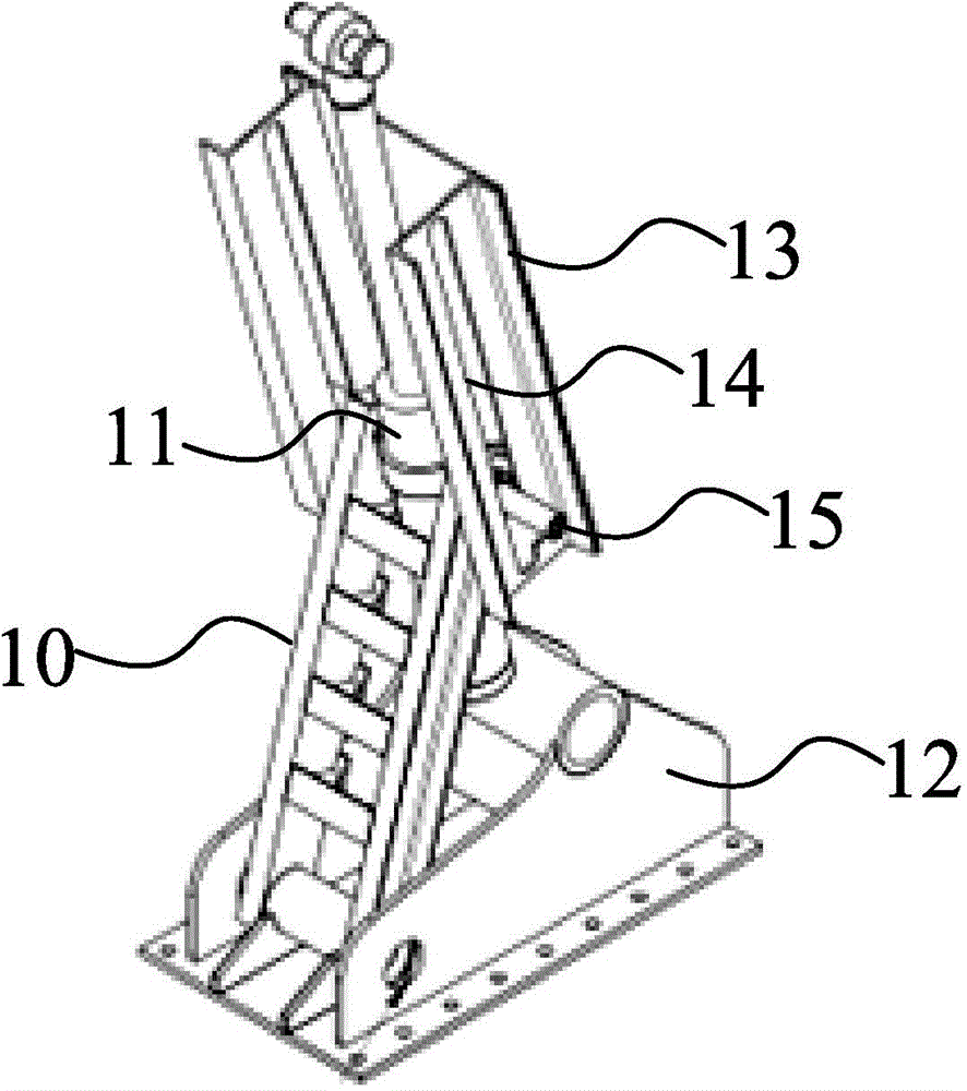
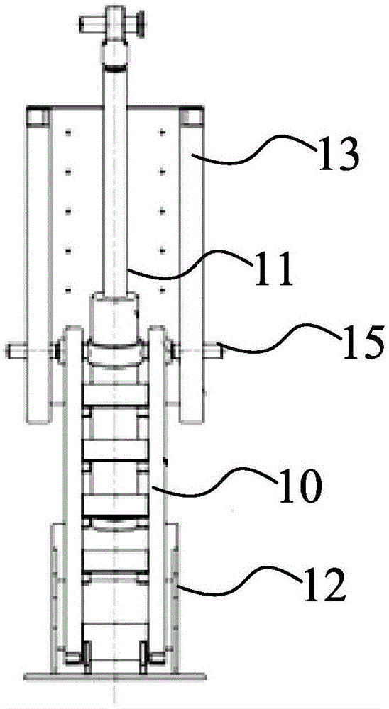
[0029] figure 2 It is a structural schematic diagram of the power unit of the hinge movable dam according to an embodiment of the present invention. image 3 for figure 2 Another state diagram of the power unit of the hinge movable dam of the illustrated embodiment. Such as figure 2 with image 3 As shown, the power unit of the hinge ...


PUM


Abstract

The invention provides a hinged movable dam and a power unit thereof. The power unit of the hinged movable dam comprises a tappet rod, a hydraulic cylinder, a guide groove structure and a bottom shaft base, wherein the guide groove structure comprises a groove body and a pair of parallel guiding grooves formed in the groove body; one end of the tappet rod is connected with one end of the hydraulic cylinder through a sliding bearing, and the other end of the tappet rod is connected with the bottom shaft base through a hinge; the back of the groove body is fixedly arranged on a gate body of the hinged movable dam, and the bottom shaft base is connected with a foundation connecting plate of a hinge dam; the hydraulic cylinder is used for pushing the sliding bearing to slide upwards or downwards along the guiding grooves, and thus, the tappet rod can swing around the hinge so as to drive the gate body of the hinged movable dam to rise or fall. According to the hinged movable dam and the power unit thereof, the power unit of the hinged movable dam has relatively strong stability, and the gate body can effectively resist water pressure under the supporting of the structure, so that the defect of no-instruction dam dropping of hinged movable dams in the prior art is overcome, and the flood control function of the hinged movable dam can be effectively improved.

Description

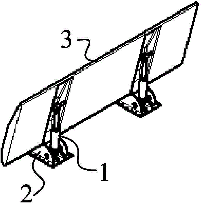
technical field [0001] The invention relates to the technical field of water conservancy engineering, in particular to a power unit of a hinge movable dam and the hinge movable dam. Background technique [0002] Movable dams are usually widely used as low-head water-retaining structures in urban flood control, landscaping, irrigation, and power generation. [0003] Hydraulic lifting dams and hinge movable dams have become more and more widely used in recent years due to reasons such as high cost performance. E.g, figure 1 It is a structural schematic diagram of a hinge movable dam in the prior art. Such as figure 1 As shown, the existing hinge movable dam includes a hydraulic cylinder 1, a bottom shaft base 2 and a gate body 3, wherein the hydraulic cylinder 1 is directly arranged on the backwater side of the gate body 3; one end is connected to the gate body 3, and the other end is connected to the bottom. Shaft base 2 connection. When the dam is raised, the hydraulic ...

Claims


Application Information

Patent Timeline
IPC IPC(8): E02B7/40E02B7/54
Inventor 陈晏育王国秋赵月芬耿晔晗刘旭冉刘杰王湛闫永生
Owner BEIJING IWHR BIC
Learn More