Shaft part on spiral track line contact surface

A technology for contacting surfaces and shaft parts. It is applied in the field of shaft parts. It can solve problems such as the difficulty in ensuring the correct fit of the guide post and the guide sleeve, the shift of the pressure center of the upper and lower molds, and the increase in the fit gap. It achieves a small gap and is easy to pull. Straight, small contact stress effect

Inactive Publication Date: 2015-08-12
SOUTH CHINA UNIV OF TECH
View PDF5 Cites 4 Cited by
  • Summary
  • Abstract
  • Description
  • Claims
  • Application Information

AI Technical Summary

Problems solved by technology

After long-term work, the thermal expansion between the guide post and guide sleeve will aggravate the wear, resulting in an increase in the fit gap and a decrease in the guiding accuracy. In addition, the unbalanced lateral force during the work of the guide post and guide sleeve will cause the upper and lower mold pressure to increase. The center is shifted, it is difficult to ensure the correct fit of the guide post and the guide sleeve
Commonly used guide post guide sleeves are divided into sliding type guide post guide sleeves and rolling type guide post guide sleeves. The sliding type guide post guide sleeves are surface contact, and the guide post guide sleeves are clearance fit, which cannot be satisfied in the process of precision stamping. The rolling type guide post and guide sleeve is to eliminate the gap, and the ball is pressed between the guide post and the guide sleeve to maintain an interference value of 0.01-0.02mm between the three , so the guidance of the upper and lower molds is accurate and reliable, and the friction force is reduced, but this will lead to difficulties in processing and assembly

Method used


Image

  • Shaft part on spiral track line contact surface
  • Shaft part on spiral track line contact surface
  • Shaft part on spiral track line contact surface

Examples


Embodiment 1

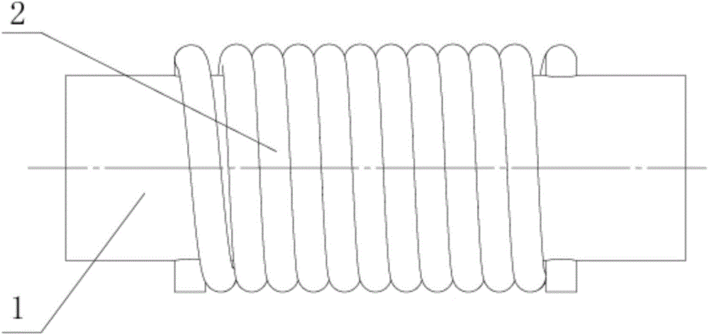
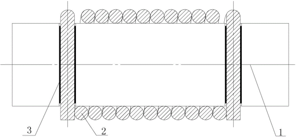
[0026] Such as figure 1 and figure 2 As shown, the shaft parts of the present invention that contact the surface of the helical track line, specifically the shaft whose surface is a helical track coating layer, include a shaft 1 and a helical track cylindrical part 2 fixed on the shaft 1, wherein , the spiral track cylindrical part 2 is spirally formed by winding the ribbon material on the shaft body of the shaft 1 along its axial direction. After forming, the outer surface of the spiral track cylindrical part 2 is the working surface of the shaft 1, and two ribbons The gap between the materials can hold the lubricant and loose particles, which greatly reduces wear and improves the service life of the parts. The two ends of the shaft 1 are respectively provided with a strip material installation hole, and the ribbon heads at the two ends of the spiral track cylindrical part 2 are respectively penetrated into the respective corresponding ribbon material installation holes, an...

Embodiment 2

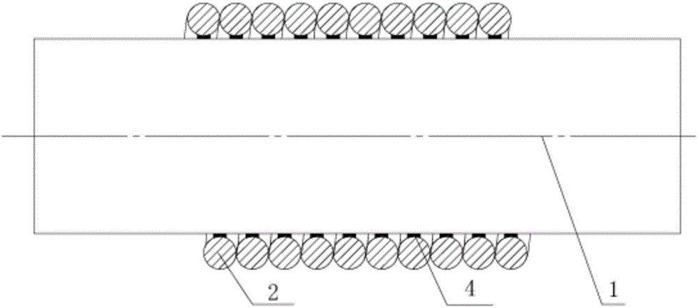
[0032] Such as image 3 As shown, the difference from embodiment 1 is that the two ends of the shaft 1 in this embodiment do not need to be provided with ribbon material installation holes, and the spiral track cylindrical part 2 is fixed by welding the ribbon material on the shaft 1 while winding it. 4 in the figure is solder.

Embodiment 3

[0034] Such as Figure 4 As shown, the difference from Example 2 is that the helical track cylindrical part 2 in this example is pasted and fixed on the shaft 1 by using a pasting material 5 (specifically, glass glue), and specifically, the pasting material 5 is first coated on the shaft 1. Material 5, and then tightly wind the ribbon material on the shaft 1.


PUM


Abstract

The present invention discloses a shaft part on the spiral track line contact surface. The shaft part comprises a shaft and a spiral track cylindrical member fixed on the shaft, wherein ribbon materials are wound on the shaft body and are subjected to spiral forming along the axis direction to form the spiral track cylindrical member, the outer surface of the spiral track cylindrical member is the working surface of the shaft after the forming, and the gap exists between the two ribbon materials and can accommodate lubricating oil and free particles. The shaft part of the present invention has characteristics of long service, large bearing capacity, and low maintenance cost.

Description

technical field [0001] The invention relates to the technical field of shaft parts, in particular to a shaft part with a helical trajectory contacting the surface. Background technique [0002] Bearings are widely used in various aspects. In these applications, the bearings bear the contact force between the connected objects, and at the same time allow the relative motion such as rotation or movement between the connected objects. In the process of relative motion, wear is inevitable, which is related to the friction force generated during the motion process between objects. The greater the friction force, the more serious the wear. Wear includes free particles scratching and embedding into the bearing surface. As the wear increases, the friction increases and the wear becomes more and more serious. Existing techniques reduce the effect of abrasion by providing a softer contact surface that allows most particles to scratch or embed to dislodge particles from the interface ...

Claims


Application Information

Patent Timeline
Patent Type & Authority Applications(China)
IPC IPC(8): F16C3/02
Inventor 周照耀姚碧波
Owner SOUTH CHINA UNIV OF TECH
Why Eureka
Try Eureka