Furnace nozzle combustion device

A combustion device and burner nozzle technology, which is applied in the direction of burners, combustion methods, combustion types, etc., can solve the problems of insufficient combustion of combustible gas, and achieve the effects of preventing escape, good mixing effect, and improving mixing effect

Active Publication Date: 2015-08-12
德龙(肇庆)科技有限公司
5 Cites 2 Cited by

AI-Extracted Technical Summary

Problems solved by technology

[0005] In order to overcome the defects of insufficient combustible gas combustion in the prior art, the present invention proposes a burner no...

Abstract

The invention discloses a furnace nozzle combustion device. The furnace nozzle combustion device sequentially comprises an air chamber, a combustion cavity and a combustion nozzle which are connected in a sealed mode. A gas inlet and an oxygen inlet are formed in the air chamber, the air chamber is a cylinder, a mixed gas outlet connected with the combustion cavity is formed in the end face of one side of the cylinder, the gas inlet is formed in the center of the end face of the other side of the cylinder and connected with the tail end of a combustible gas channel, and the oxygen inlet is formed in the side face of the cylinder and connected with an oxygen supply pipe in a sealed mode. By the adoption of the furnace nozzle combustion device, air is fully mixed with combustible gas through the oxygen inlet, the mixing effect is good, and therefore the combustible gas is burnt completely.

Application Domain

Gaseous fuel burner

Technology Topic

Oxygen supplyFuel gas +4

Image

  • Furnace nozzle combustion device
  • Furnace nozzle combustion device

Examples

  • Experimental program(1)

Example Embodiment

[0028] The structure of the present invention will be explained in detail below in conjunction with the accompanying drawings.
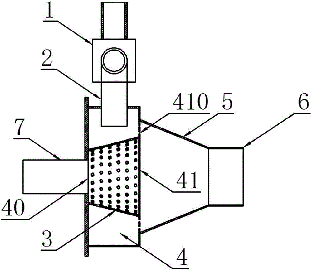
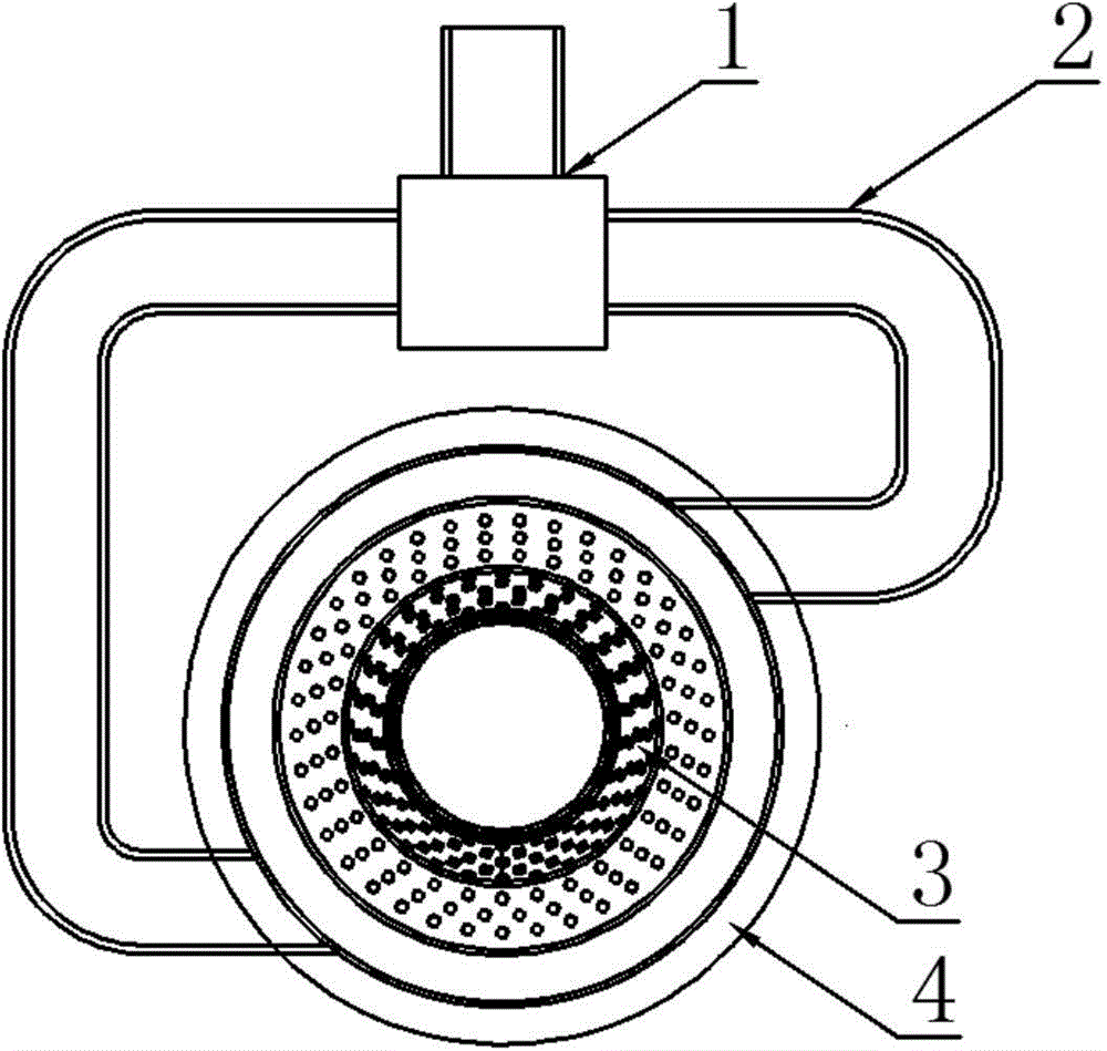
[0029] like figure 1 , 2 A burner nozzle combustion device shown includes an air chamber 4, a combustion chamber 5, and a burner 6 that are sealed and connected in sequence. Relatively speaking, the air chamber 4 is a large cylinder, and the burner 6 is a small cylinder. Cavity 5 is a conical cylinder, the large mouth of the conical cylinder faces the air chamber 4, and the small mouth of the conical cylinder faces the burner 6. This way can increase the density of the mixture at the burner 6, which is beneficial to ignite the mixture.
[0030] The air chamber 4 is provided with a mixing chamber 3, the mixing chamber 3 is a cone-shaped mesh cylinder, and the air chamber 4 is provided with a gas inlet 40, an oxygen inlet and a mixed gas outlet 41, which are respectively used for the entry of combustible gas, air and mixed gas. outflow. The mixed gas outlet 41 includes an outlet at the wide end of the mixing chamber 3 and an oxygen inlet hole 410 , and the oxygen inlet hole 410 is arranged on the annular plate between the air chamber 4 and the combustion chamber 5 . In order to further improve the mixing effect, the diameter of the narrow end of the mixing chamber 3 of the present invention is larger than the diameter of the combustible gas channel 7 .
[0031] In this embodiment, the air chamber 4 is a cylinder, one end surface of the cylinder is provided with a mixed gas outlet 41, and the mixed gas outlet 41 is connected to the combustion chamber 5, and the center of the other side end surface of the cylinder is provided with a gas inlet 40, and the gas inlet 40 is connected to the end of the combustible gas channel 7; the side of the cylinder is provided with an oxygen inlet, and the oxygen inlet is sealed and connected to the oxygen supply pipe 2; Outlet 41 , the size of the mixed gas outlet 41 is larger than that of the gas inlet 40 .
[0032] The outlet direction of the oxygen supply pipe 2 of the present invention is tangent to the outer surface of the mixing chamber 3 . That is to say, the gas coming out of the oxygen supply pipe 2 enters the mixing chamber 3 after passing through the mesh tangentially, forming a swirling wind in the mixing chamber 3. Since the gas pressure coming out of the oxygen supply pipe 2 is relatively high, the speed of the gas rotation Faster, fully mixed with combustible gas, and burns more fully in the combustion chamber 5 and the burner 6. Moreover, because the gas pressure from the oxygen supply pipe 2 is greater than the pressure of the combustible gas, the combustible gas is confined in the mixing chamber 3 and will not run into the space between the air chamber 4 and the mixing chamber 3, and the combustible gas and air are also Mix in the mixing chamber 3, and the mixed gas is discharged from the gas outlet 41, and then burns in the combustion chamber 5 and the burner 6.
[0033] In order to provide more sufficient air and facilitate the adjustment of the air supply, there are two oxygen inlets on the side of the cylinder in this embodiment. In order to supply air evenly, these two oxygen inlets are arranged symmetrically about the axis of the cylinder. The air supply can be adjusted according to the amount of combustible gas output. Of course, multiple oxygen inlets can be provided according to actual needs, so as to provide rotating wind with greater wind speed.
[0034] In order to simplify the connection of the device and save the length of the oxygen supply pipe 2, the oxygen supply pipe 2 connected to the two oxygen inlets is connected to the two outlets of the three-way pipe joint 1, and the entrance of the three-way pipe joint 1 can be connected to the fan through a pipe or directly , so only one fan with one air outlet is needed to meet the needs of the device of the present invention. If multiple oxygen inlets are used, then multiple oxygen supply pipes 2 are required, and a multi-way pipe joint or multiple parallel multi-way pipe joints may be required, whichever can achieve the purpose of the invention.
[0035] The above descriptions are only preferred embodiments of the present invention, and are not intended to limit the present invention. Any modifications, equivalent replacements and simple improvements made on the essence of the present invention should be included in the protection scope of the present invention. Inside.

PUM

no PUM

Description & Claims & Application Information

We can also present the details of the Description, Claims and Application information to help users get a comprehensive understanding of the technical details of the patent, such as background art, summary of invention, brief description of drawings, description of embodiments, and other original content. On the other hand, users can also determine the specific scope of protection of the technology through the list of claims; as well as understand the changes in the life cycle of the technology with the presentation of the patent timeline. Login to view more.

Similar technology patents

Single slip soluble bridge plug

Owner:FIVE STAR DOWNHOLE SERVICE INC +1

Ship waste gas denitration system

InactiveCN106640291Ashorten the lengthReduce the set of connectors
Owner:SUNRUI MARINE ENVIRONMENT ENG

Compact large diesel engine tail gas treatment device and method

InactiveCN108798852Ashorten the lengthsave space
Owner:山东康钧环保科技有限公司

Classification and recommendation of technical efficacy words

  • shorten the length
  • good mixing effect

Integral fuel jet radial swirler pre-mixing preevaporated low pollution combustion-chamber

InactiveCN101285591Ashorten the lengthWide stable working range with low
Owner:BEIHANG UNIV

Construction method for high face mining support removing passage under complicated geological condition

InactiveCN102312676Ashorten the lengthsuitable selection
Owner:SHANXI JINCHENG ANTHRACITE COAL MINING GRP CO LTD

Silicon carbide avalanche photodiode with novel small-dip-angle half mesa structure

ActiveCN104882510Ashorten the lengthImprove fill factor
Owner:苏州镓敏光电科技有限公司
Why Eureka
Try Eureka