Vertical parallelometer

A technology of collimator and vertical part, which is applied in the field of vertical collimator, can solve the problems of obsolete functions and reduced use value, and achieve the effects of small environmental factors, strong stability, and simple and convenient installation and adjustment

Inactive Publication Date: 2015-08-12
东莞市鼎先激光科技股份有限公司
View PDF7 Cites 8 Cited by
  • Summary
  • Abstract
  • Description
  • Claims
  • Application Information

AI Technical Summary

Problems solved by technology

The important point is that the assembly of the resonant cavity only uses the single function of the ver

Method used


Image

  • Vertical parallelometer
  • Vertical parallelometer
  • Vertical parallelometer

Examples


Example Embodiment

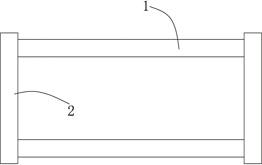
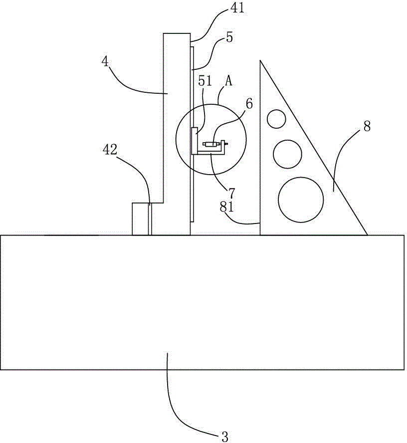
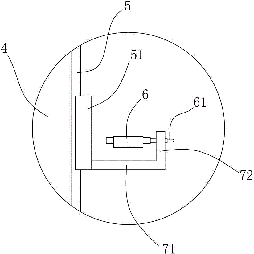
[0021] Example: such as figure 2 with image 3 As shown, a vertical parallel instrument of the present invention includes a marble platform 3 on which an L-shaped marble base 4 is movably provided on the side of the L-shaped marble base 4 perpendicular to the marble platform 3 A guide rail 5 is arranged longitudinally on the guide rail 5, a dial indicator 6 is movably arranged on the guide rail 5, and the dial indicator 6 is arranged horizontally, and the probe 61 of the dial indicator 6 and the L-shaped marble substrate The side 41 of 4 is perpendicular to and away from the side 41.

[0022] The bottom surface of the L-shaped marble base 4 is provided with an air blowing groove, and the L-shaped marble base 4 is provided with an air blowing hole 42 communicating with the blowing groove.

[0023] The blowing hole 42 is connected with an air pump.

[0024] The guide rail 5 is provided with a sliding block 51, a gauge base 7 is fixed on the sliding block 51, and the dial indicator 6...


PUM


Abstract

The invention discloses a vertical parallelometer. The vertical parallelometer comprises a marble platform. An L-shaped marble substrate is movably arranged on the marble platform. A guide rail is longitudinally arranged on a side surface, perpendicular to the marble platform, of the L-shaped marble substrate. A dial gauge capable of moving up and down is arranged on the guide rail. The dial gauge is horizontally arranged. A measuring head of the dial gauge is perpendicular to the side surface of the L-shaped marble substrate and is opposite to the side surface. According to the invention, the structure is simple, the design is reasonable and ingenious, the marble material is high in stability, environment factors have little influence on the marble material, and the marble material is easy to machine and relatively low in cost. The installation adjustment of the precise linear guide rail is relatively simple and convenient, an ordinary person understanding a little of the mechanical principle can carry out adjustment and self-correction to ensure the usage precision, and the vertical parallelometer is relatively practical. The integrated manufacturing cost is less than one tenth of that of an imported height instrument, so that the vertical parallelometer is rather economic and practical for occasions having usage requirements of verticality, parallelism and linearity.

Description

technical field [0001] The invention relates to a high-power gas laser, in particular to a vertical parallelizer, which is used to install and debug the core component resonant cavity of the high-power gas laser. Background technique [0002] The resonant cavity is the core component of a high power gas laser, and is usually installed in a frame structure, which supports the entire resonant cavity. Usually, the resonant cavity can be fixed into the frame structure by hanging or supporting, and the experiment shows that the supporting method is better. [0003] Such as figure 1 Shown is a common frame structure at present. This frame structure is commonly known as a light bridge. It is composed of three or four light bridge tubes 1 and end plates 2 at left and right ends. The light bridge tubes 1 play a supporting role and stabilize the end plates 2 at both ends. The output mirror, reflecting mirror and the adjusting mechanism of the output mirror and reflecting mirror of t...

Claims


Application Information

Patent Timeline
IPC IPC(8): G01B5/245
Inventor 王艳春朱小明张永青
Owner 东莞市鼎先激光科技股份有限公司
Why Eureka
Try Eureka