A metal grid frequency selective surface structure and its manufacturing method

A frequency selective surface and metal grid technology, applied in the field of optical windows, can solve the problems of reducing the light transmission performance, reducing the light transmission performance and electromagnetic shielding performance of the frequency selective surface structure of the metal grid, and uneven distribution of high-order diffraction energy. , to achieve the effect of improving light transmission performance

Active Publication Date: 2017-07-28
HARBIN INST OF TECH
View PDF4 Cites 0 Cited by
  • Summary
  • Abstract
  • Description
  • Claims
  • Application Information

AI Technical Summary

Problems solved by technology

[0011] In view of the above-mentioned shortcomings and deficiencies, the present invention discloses a metal grid frequency selective surface structure and a manufacturing method. The method not only avoids the use of titanium dioxide solution, but also avoids the problem of reducing the light transmission performance of the metal grid frequency selective surface structure due to the increase of the metal line width. problem, and there is no need to remove the template by mechanical friction, avoiding the traditional mechanical friction method while reducing the light transmission performance and electromagnetic shielding performance of the frequency selective surface structure of the metal grid, and also provides specific solutions to the problem of uneven distribution of high-order diffraction energy The processing conditions make the metal grid frequency selective surface structure produced by the method of the present invention not only have good electromagnetic shielding performance, but also achieve the effect of no obvious diffraction when solving the problem of uneven distribution of high-order diffraction energy, with good Light transmission performance

Method used


Image

  • A metal grid frequency selective surface structure and its manufacturing method
  • A metal grid frequency selective surface structure and its manufacturing method
  • A metal grid frequency selective surface structure and its manufacturing method

Examples


specific Embodiment 1

[0051] This embodiment is an embodiment of a metal grid frequency selective surface structure.

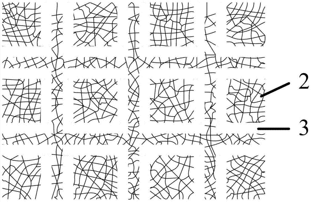
[0052] The frequency-selective surface structure of the metal grid of this embodiment includes a substrate 1, a transparent grid film 2 distributed on the substrate 1, and the surface of the transparent grid film 2 has a periodic opening array 3;

[0053] The shape of the transparent grid film 2 is a pattern formed by natural drying of the cracked nail polish containing acrylic resin at a temperature of 20-25°C and a humidity of 50-80%RH;

[0054] The inside of the periodic opening array 3 has one of the following two structures:

[0055] Structure 1. No transparent mesh film 2;

[0056] Structure 2: Containing a transparent mesh film 2, the transparent mesh film 2 inside the hole and the transparent mesh film 2 outside the hole are not connected.

[0057] Here, the periodic opening array 3 is a square ring, the periodic opening array 3 contains a transparent mesh film 2 inside, and the trans...

specific Embodiment 2

[0059] This embodiment is still an embodiment of the metal grid frequency selection surface structure.

[0060] The frequency selective surface structure of the metal grid of this embodiment includes a substrate 1, a transparent grid film 2 and a periodic opening array 3 distributed on the substrate 1; the transparent mesh film 2 and the periodic opening array 3 are The exchange of corresponding positions described in the first embodiment.

specific Embodiment 3

[0062] This embodiment is an embodiment of a method for manufacturing a frequency selective surface structure of a metal grid.

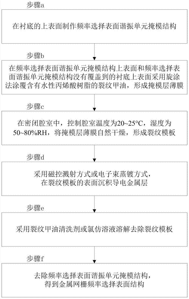
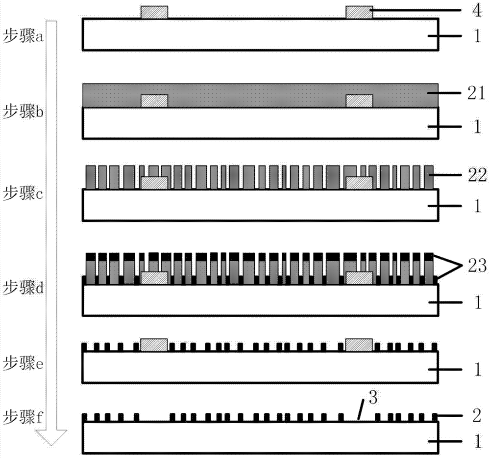
[0063] The manufacturing method of the frequency selective surface structure of the metal grid of this embodiment, the flowchart is as figure 2 Shown. The method includes the following steps:

[0064] Step a, fabricating a frequency selective surface resonance unit mask structure 4 on the upper surface of the substrate 1;

[0065] In step b, the upper surface of the frequency selective surface resonant unit mask structure 4 and the upper surface of the substrate 1 not covered by the frequency selective surface resonant unit mask structure 4 are coated with a crack nail polish containing water-based acrylic resin by a spin coating method to form Mask layer film 21;

[0066] Step c, in a closed chamber, the temperature of the chamber is controlled to be 20-25°C and the humidity is 50-80%RH, and the mask layer film 21 is naturally dried to form a crack templa...


PUM


Abstract

The invention discloses a metal mesh frequency selection surface structure and a manufacturing method, and belongs to the technical field of optical windows. The structure comprises a substrate, and a transparent mesh film which is distributed on the surface of the substrate and has a periodic hole array. The method comprises the steps: manufacturing a frequency selection surface resonance unit mask structure on the upper surface of the substrate firstly; employing a coating method to coat crack nail polish containing aqueous acrylic resin, thereby forming a mask film; enabling mask liquid to be naturally dried to form a crack template under the specific conditions secondly; depositing a conductive metal layer on the surface of the crack template thirdly; and sequentially dissolving the crack template, removing the frequency selection surface resonance unit mask structure, and obtaining the structure finally. The structure and method not only solve a problem of reducing the light transmittance performance of an optical window because of the increase of the width of a metal wire, but also prevent a conventional mechanical friction mode from reducing the light transmittance performance and the electromagnetic shielding performance of the optical window at the same time. Moreover, the specific machining conditions for solving a problem of the uneven distribution of the high-order diffraction energy are given.

Description

Technical field [0001] A metal grid frequency selective surface structure and a manufacturing method belong to the technical field of optical windows. Background technique [0002] Optical windows are widely used in remote sensing, medical diagnosis, confidential communication, aerospace equipment and other fields. The traditional optical window is a pure electromagnetic wave transmission window. However, the continuous growth of electrical equipment will not only greatly increase the intensity of electromagnetic waves, but also broaden the band of electromagnetic waves, causing the electromagnetic environment of space to deteriorate day by day. Because traditional optical windows have permeability to electromagnetic waves, the electromagnetic environment deteriorates Will adversely affect electromagnetically sensitive equipment. In order to reduce electromagnetic interference, an electromagnetic shielding function needs to be added to the optical window. In the prior art, a m...

Claims


Application Information

Patent Timeline
Patent Type & Authority Patents(China)
IPC IPC(8): G02B5/18H01P1/20
CPCG02B5/18G02B5/1847H01P1/20
Inventor 韩余金鹏
Owner HARBIN INST OF TECH
Why Eureka
Try Eureka