Carrier phase shift based control system modeling method for modular multilevel converter (MMC)
A modular multi-level, carrier phase shift technology, applied in the fields of instruments, electrical digital data processing, special data processing applications, etc. Avoiding dimensional conversion work, avoiding dimensional conversion work, effect of reliable data communication
- Summary
- Abstract
- Description
- Claims
- Application Information
AI Technical Summary
Problems solved by technology
Method used
Image
Examples
Embodiment 1
[0035] In this embodiment, a CPS-SPWM-based MMC control system designed in a PSCAD environment is used to illustrate the modeling method of the present invention.
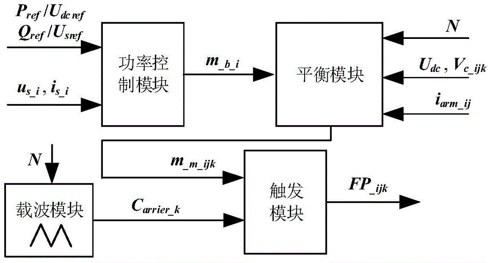
[0036] Step 1: Divide the MMC packaging control system based on CPS-SPWM into 4 packaging control modules, namely power control module, balance control module, carrier module and trigger module.
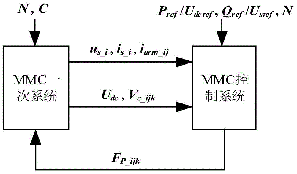
[0037] The signal interaction between the primary system and the secondary system of the existing MMC is as attached figure 1 Shown. Among them, the subscript i=A,B,C, indicating three-phase ABC; j=u or l, indicating the upper bridge arm or the lower bridge arm, respectively; k=1,2,...,N, indicating the number of the bridge arm neutron module . The meanings of the subscripts i, j and k in the present invention are the same as here.
[0038] Attached figure 1 The primary MMC system includes 6 MMC equivalent bridge arm models, and its main parameters include the number of sub-modules in a bridge arm N and the sub-module capacita...
Embodiment 2
[0061] This embodiment uses a three-terminal MMC-HVDC system to verify the dynamic characteristics of the package control system established according to the method of the present invention. As attached Figure 4 As shown, MMC has 100 sub-modules in each bridge arm, and the DC voltage is 200kV. The resistance and inductance of the DC transmission line are 0.15Ω and 25mH. MMC 1 And MMC 2 Access active AC system U s1 And U s2 In, where U s1 = U s2 =110kV, X L =j3.14Ω. MMC 3 Supply power to passive AC loads, where Z Load =(363.0+j121.0)Ω. The capacitance in each sub-module is 3mF, and the bridge arm inductance is 40mH. MMC 1 And MMC 2 use image 3 The d-q decoupling controller shown and MMC 3 Using M-δ controller. MMC 1 Use constant active and reactive power control, where P ref = 100MW, Q ref = 30Mvar. MMC 2 Adopt constant DC voltage and reactive power control, where U dcref =200kV, Q ref = 10Mvar. MMC 3 Use constant AC voltage amplitude control, where U sref = 89.8kV. ...
PUM
 Abstract
Description
Claims
Application Information
 - R&D
- Intellectual Property
- Life Sciences
- Materials
- Tech Scout
- Unparalleled Data Quality
- Higher Quality Content
- 60% Fewer Hallucinations
Browse by: Latest US Patents, China's latest patents, Technical Efficacy Thesaurus, Application Domain, Technology Topic, Popular Technical Reports.
© 2025 PatSnap. All rights reserved.Legal|Privacy policy|Modern Slavery Act Transparency Statement|Sitemap|About US| Contact US: help@patsnap.com


