Arc extinguish chute, arc extinguish chamber and breaker

A technology of arc extinguishing grid and arc extinguishing chamber, which is applied in the direction of circuit breaker components, circuits, electrical components, etc., which can solve the problem that the circuit breaker cannot meet the arc extinguishing effect and arc ignition speed at the same time, so as to avoid blockage and avoid blockage Effect

Inactive Publication Date: 2015-08-12
DELIXI ELECTRIC
View PDF7 Cites 18 Cited by
  • Summary
  • Abstract
  • Description
  • Claims
  • Application Information

AI Technical Summary

Problems solved by technology

[0004] Therefore, the technical problem to be solved by the present invention is that the existing circuit breaker cannot meet the technical defects of stable arc extinguishing effect and

Method used


Image

  • Arc extinguish chute, arc extinguish chamber and breaker
  • Arc extinguish chute, arc extinguish chamber and breaker
  • Arc extinguish chute, arc extinguish chamber and breaker

Examples


Example Embodiment

[0028] Example 1

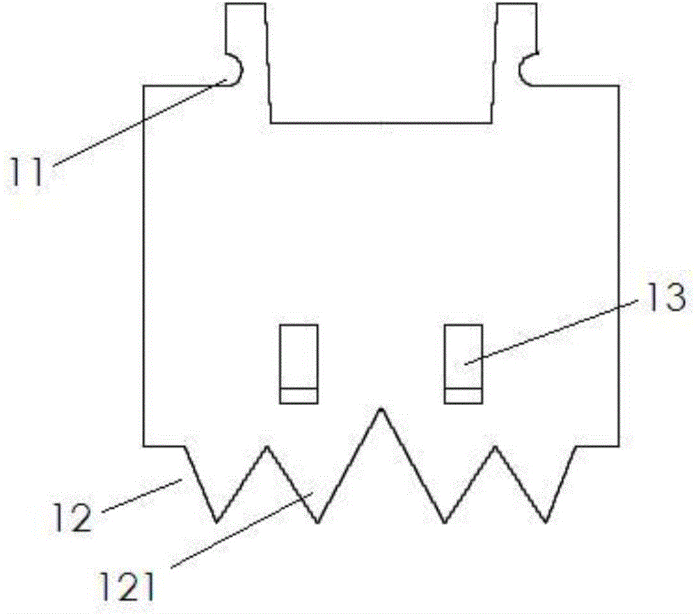
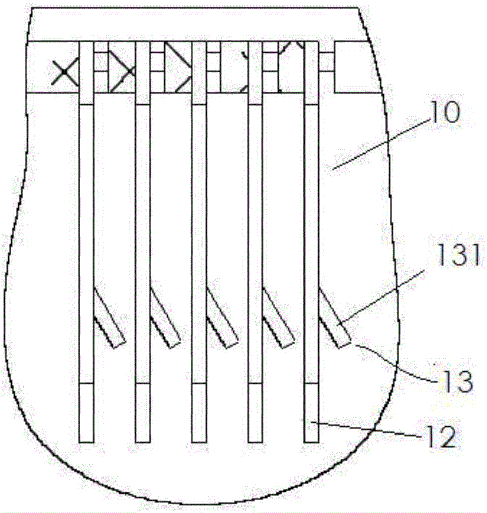
[0029] This embodiment provides an arc extinguishing grid, refer to figure 1 and figure 2 , the arc extinguishing grid includes a sheet-shaped grid body 10, in figure 1 In the state shown, the upper end of the grid body 10 is provided with a mounting part 11 for buckling or clamping, and the lower end of the grid body 10 is formed with an arc striking part 12 along the length direction. The grid body 10 is further formed with at least one protruding portion 13 protruding from the surface of the grid body 10 and obliquely disposed on the grid body 10 between the mounting portion 11 and the arc leading portion 12 .

[0030] refer to figure 2 The schematic diagram of the working state of the arc extinguishing grid in the arc extinguishing chamber is shown, when the arc is attracted to the arc through the arc strike plate 30 figure 2 When the leftmost grid body 10 shown is on the grid body 10, since the electrical distance between the protruding portion 1...

Example Embodiment

[0037] Example 2

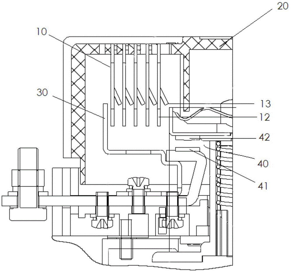
[0038] This embodiment provides an arc extinguishing chamber, refer to figure 2 , the arc extinguishing chamber of this embodiment includes an arc extinguishing cover 20, and in the arc extinguishing cover 20, several arc extinguishing grids described in Embodiment 1 are arranged in parallel at intervals, and the protruding part on each grid body 10 13 protrudes toward the side where the arc is generated, and the protruding part 13 is not in contact with the adjacent grid body 10; it also includes an arc strike plate 30 for striking the arc to the arc extinguishing grid, wherein the arc is generated At image 3 , Figure 4 The contact assembly 40 is shown.

[0039] Further, the distance between adjacent grid bodies 10 is the same, and the distance is 2-4.5 mm.

[0040] As an implementation, when the circuit breaker or contactor is of large capacity, the distance between each grid body 10 can be selected but not limited to 3-4.5mm; when the circuit break...

Example Embodiment

[0043] Example 3

[0044] This implementation provides a circuit breaker, including: the arc extinguishing chamber described in Embodiment 2, and a contact assembly 40, the arc strike plate 30 in the arc extinguishing chamber is close to the static contact 41 in the contact assembly 40 It is provided that the end of the arc strike plate 30 extends close to the one of the arc extinguishing grids that is furthest from the contact assembly 40 .

[0045] Further, the protruding portion 13 of the arc extinguishing grid which is closest to the contact assembly 40 is arranged close to the movable contact 42 of the contact assembly 40 .

[0046] Further, the moving contact 42 is a bridge contact.

[0047] The arc extinguishing process of the circuit breaker of this embodiment is as follows:

[0048] refer to image 3 , 4 , the arc is generated at the contact assembly 40. After the arc is generated, a part of the arc passes through the moving contact 42 and is guided by the protrud...


PUM


Abstract

The invention discloses an arc extinguish chute, an arc extinguish chamber and a breaker. The arc extinguish chute comprises a plate-like grid sheet main body. An installing part convenient for buckling or holding is arranged at one end of the grid sheet main body, and a plurality of arc strike parts for striking arc are formed on the other end of the grid sheet main body along the length direction, and at least one arc extinguish chute, which is protruded at the extension part of the grid sheet main body, is formed between the installing part and the arc strike part. Because the extension part is adopted, the arc chute, distances among the adjacent arc extinguish chutes are shortened so that arc extinguishing can be easily and fast. Therefore, different from the prior art, the arc extinguish chute only needs to shorten the distance between among the chutes so as to extinguish arc fast without sacrificing the distances among the chutes, thereby avoiding a congestion problem. Therefore, a congestion avoiding effect and a fast arc extinguishing effect can be achieved simultaneously.

Description

technical field [0001] The invention relates to an arc extinguishing grid, an arc extinguishing chamber and a circuit breaker, and belongs to the technical field of low-voltage electrical appliances. Background technique [0002] During the breaking process of the circuit breaker, an arc will be generated between the moving contact and the static contact. Since the arc is conductive, if it cannot be extinguished in time, it will directly affect the current limiting capacity of the circuit breaker and reduce the breaking capacity, thereby affecting the circuit breaker. The service life of the device, or even endanger personal safety. Therefore, in order to ensure the safety of electricity use, a circuit breaker is often used in the circuit breaker to extinguish the generated arc. [0003] Existing circuit breakers generally adopt the grid short-arc principle, relying on the magnetic field generated by the contact conductive circuit to drive the arc into the arc extinguishing...

Claims


Application Information

Patent Timeline
IPC IPC(8): H01H9/34H01H73/18
CPCH01H9/34H01H73/18
Inventor 李新叶晏恒明郑天云周大君
Owner DELIXI ELECTRIC
Why Eureka
Try Eureka