
air conditioner

An air-conditioning and load-side technology, applied in the field of control to reduce power consumption, can solve the problems of reduced energy-saving effect and increased power consumption of blowers, and achieve the effect of improving energy-saving effect

Active Publication Date: 2018-09-04
MITSUBISHI ELECTRIC CORP
View PDF6 Cites 0 Cited by
  • Summary
  • Abstract
  • Description
  • Claims
  • Application Information

AI Technical Summary

Problems solved by technology

[0010] In addition, if the condenser and the evaporator are operated at high rotational speeds of the air blowers of the condenser and evaporator in order to control the condensation temperature and the evaporation temperature of the control target, there is a problem that the power consumption of the air blower is lower than the power consumption of the compressor. Relatively increased, as a result, the energy-saving effect is reduced

Method used


Image

  • air conditioner
  • air conditioner
  • air conditioner

Examples


Embodiment approach

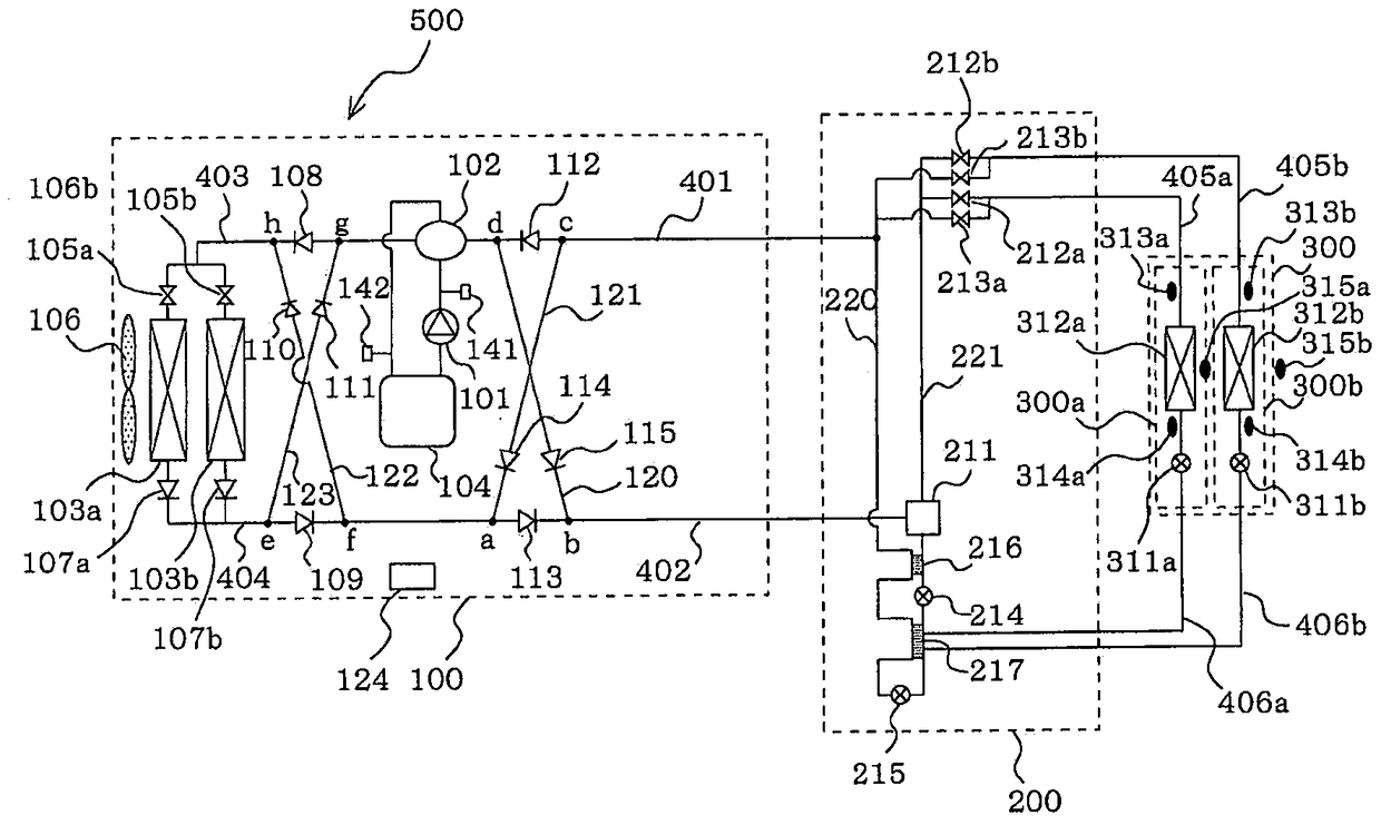
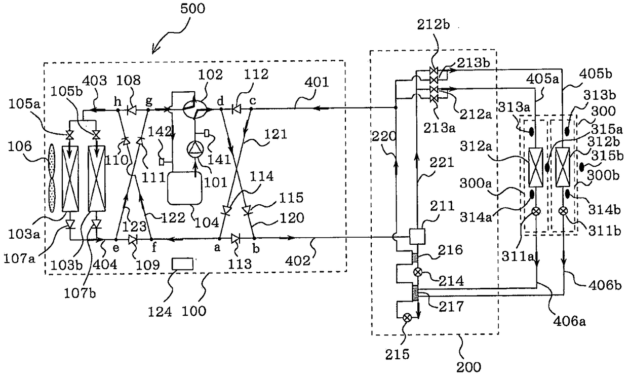
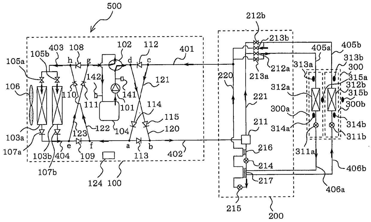
[0024] figure 1 It is a schematic configuration diagram showing an example of the refrigerant circuit configuration of the air-conditioning apparatus 500 according to the embodiment of the present invention. according to figure 1 , the refrigerant circuit structure of the air-conditioning apparatus 500 will be described. In addition, contains figure 1 In addition, in the following drawings, the size relationship of each component may be different from the actual situation.

[0025] This air conditioner 500 is installed in a building, an apartment, or the like, and can perform cooling and heating mixed operation by utilizing a refrigeration cycle (heat pump cycle) that circulates a refrigerant. The air conditioner 500 is composed of a heat source side unit 100, a refrigerant control unit 200, and a plurality of units (in figure 1 In the middle are two) load-side units 300 (300a, 300b).

[0026] In addition, the heat source side unit 100 and the refrigerant control unit...


PUM


Abstract

A target condensing temperature and a target evaporating temperature are changed in accordance with a load of each load side unit 300 obtained by using load detection means 315, and an operating frequency of a compressor 101 and a rotation speed of a fan 106 are controlled such that a condensing temperature obtained by using temperature detection means coincides with the target condensing temperature and an evaporating temperature obtained by using the temperature detection means coincides with the target evaporating temperature.

Description

technical field [0001] The present invention relates to a multi-type air conditioner capable of performing cooling operation or heating operation by each of a plurality of indoor units (load-side units) (hereinafter referred to as cooling and heating mixed operation), and particularly relates to reduction of power consumption control method. Background technique [0002] Conventionally, there is an air-conditioning apparatus in which the evaporating temperature and the condensing temperature, which are control targets in the refrigeration cycle, are variable according to the load (see Patent Document 1). This air conditioner uses the load of the air conditioner estimated from the operating mode and the difference between the set temperature and the suction temperature, and sets the control target temperature, evaporating temperature and condensing temperature, to variable values, and performs a low compression ratio at low load. operation, reducing power consumption. [00...

Claims


Application Information

Patent Timeline
Patent Type & Authority Patents(China)
IPC IPC(8): F24F11/64F25B1/00F25B49/02F24F110/10
CPCF25B1/00F24F11/30F24F11/62F24F11/89F24F2110/10F25B13/00F25B49/02F25B2313/0231F25B2313/0233F25B2313/0253F25B2313/0272F25B2313/02741F25B2313/0293F25B2313/0294F25B2313/0314F25B2400/13F25B2400/23F25B2600/0253F25B2600/19F25B2600/21F25B2700/1931F25B2700/1933F24F11/77F24F11/85Y02B30/70F25B5/02F25B2313/023F25B2313/025F25B2313/02531F25B2313/02533F25B2600/025F25B2600/111F25B2600/112F25B2700/2104F25B2700/2116F25B2700/2117
Inventor 冈野博幸
Owner MITSUBISHI ELECTRIC CORP
Learn More