
Film preparation device and observation method for film growth

A thin film preparation and coating room technology, which is applied to the equipment that forms a thin film on the surface, indirectly observes the film formation process on the film forming surface, and observes the field of film growth. Problems affecting membrane performance, etc., to achieve the effect of simple structure, small opening, and convenient operation

Inactive Publication Date: 2010-03-17
天津佰腾生产力促进中心有限公司
View PDF1 Cites 0 Cited by
  • Summary
  • Abstract
  • Description
  • Claims
  • Application Information

AI Technical Summary

Problems solved by technology

However, when preparing different films in different equipment, it is necessary to re-establish vacuum working conditions, so the energy consumption is high and the efficiency is low.
Another shortcoming of the existing equipment is that when the film is annealed after preparation, the film sample needs to be taken out of the coating chamber and placed in another annealing heating device for annealing, which not only has low efficiency and high energy consumption, but also It will affect the performance of the film to a certain extent; since the film annealing treatment is also required to be carried out under vacuum conditions in some cases, it is also necessary to re-establish the vacuum working conditions
In addition, the existing film-making equipment cannot observe the growth of the film during the process implementation. To master the thickness of the film, the film-forming process parameters are generally controlled according to empirical values. Control the evaporation temperature and time of the evaporation source empirically to control the growth rate of the film thickness and the possible thickness of the film, and then take out the sample for actual measurement to obtain the vacuum thickness of the film
It can be seen that it is difficult to control the thickness of film growth by using the existing technology in actual application, and the efficiency is very low

Method used


Image

  • Film preparation device and observation method for film growth
  • Film preparation device and observation method for film growth
  • Film preparation device and observation method for film growth

Examples


Embodiment Construction

[0019] The present invention is illustrated below in combination with embodiments and accompanying drawings.

[0020] The vacuum system and electrical system in the thin film preparation device of the present invention are the same as those of the prior art, and will not be described in detail here. Only the coating chambers of the present invention and the prior art are explained here.

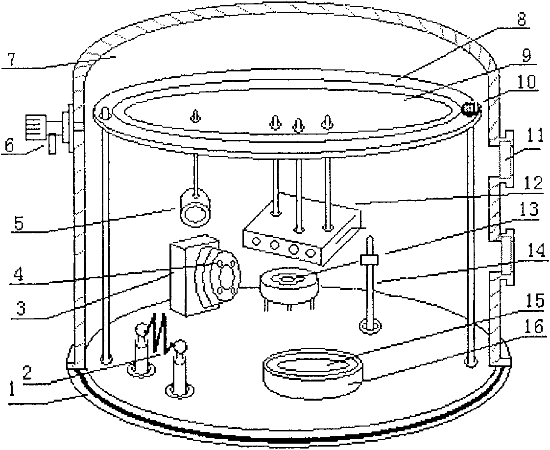
[0021] attached figure 1 It is a sectional view of an embodiment of the coating chamber of the present invention. Wherein: 2 is a resistance heating evaporator, 3 is a camera, 4 is an interference light source positioned next to the camera, 14 is used to set the rotating shaft of the rotating baffle (the baffle on it is not shown), and 15 is the sputtering target anode , 16 is the sputtering target cathode. These devices are all arranged on the bottom plate 1 of the coating chamber. Additionally, by figure 1 It can be seen that the radiant crucible evaporation heater 13 is fixed on the bo...


PUM


Abstract

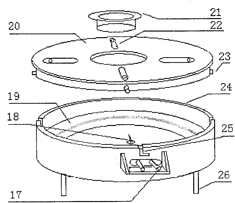
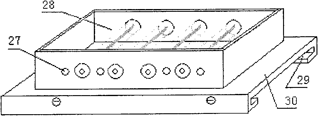
The invention discloses a device adopting a physical method to prepare films on substrate material, and a method of observing film growth condition in the preparation process. A plating chamber in thedevice of the invention is consisted of a plating chamber shell and a bottom plate under the plating chamber shell. A charge valve and an observation window are arranged on a vacuum shell. A resistance heating evaporator, a radiar crucible evaporator, a sputtering target, an interference light source and a webcam are separately arranged on the bottom plate. A rotating tray driven by a rotation axis, a sample annealing heater and a device for fixing a making film sample arranged by the bottom of the sample annealing heater are arranged on a fixing frame. The method of the invention is that aninterference phenomenon formed on the film is observed when the film grows.

Description

technical field [0001] The invention relates to a device for preparing a thin film on a base material by using a physical method, and a method for observing the growth of the film during the preparation process. More precisely, the present invention relates to a device for forming a thin film on the surface of a base material by means of vacuum deposition evaporation or vacuum sputtering deposition, and using this device to indirectly observe the film-forming surface film during the preparation process. method of forming the process. Background technique [0002] Thin film materials have a wide range of applications in the research and manufacture of new optoelectronic devices. The process of forming a thin film on the surface of the base material by vacuum sputtering deposition is relatively common at this stage. The thin films mentioned here include metal thin films, non-metallic thin films, and organic thin films. Existing thin film preparation equipment includes vacuu...

Claims


Application Information

Patent Timeline
Patent Type & Authority Patents(China)
IPC IPC(8): C23C14/24C23C14/52
Inventor 宋长安彭应全宋毅朋兴平覃同
Owner 天津佰腾生产力促进中心有限公司
Learn More