Engagement cooling apparatus of extruder

A technology of cooling device and extruder, which is applied in the field of intermeshing cooling devices, can solve the problems of insufficient heat exchange, prolonging the residence time of cooling water, and short residence time, so as to improve service life, reduce stress, increase The effect of extrusion area

Inactive Publication Date: 2015-08-19
苏州普勒新材料有限公司
View PDF4 Cites 0 Cited by
  • Summary
  • Abstract
  • Description
  • Claims
  • Application Information

AI Technical Summary

Problems solved by technology

[0002] In the paint industry, the extruder needs to use a cooler to extrude and cool the viscous and high-temperature semi-finished product during production, and make it into a thin sheet for the next step; and the existing cooler is low in cost due to the wide range of water sources Most of them use water cooling, by setting water tanks parallel to the axis on the inner wall of the driving shaft and the driven shaft, and setting multiple baffles placed at intervals in the water tank, so that the cooling water flows in the driving shaft and the driven shaft. Prolong the residence time of the cooling water in the driving shaft and the driven shaft under the obstruction of the baffle, so that the cooling water and the high-temperature semi-finished product can fully exchange heat; but this method will prolong the cooling water in the driving shaft and the driven shaft at the beginning of the work. The residence time in the shaft, once the cooling water in the water tank is full, the residence time of the cooling water in the driving shaft and the driven shaft will be very short, and the effect of exchanging heat will not be achieved. For this reason, we have developed a through The intermeshed cooling device of the extruder that increases the contact area to fully exchange heat, thereby improving the cooling effect

Method used


Image

  • Engagement cooling apparatus of extruder
  • Engagement cooling apparatus of extruder
  • Engagement cooling apparatus of extruder

Examples


Embodiment Construction

[0024] The present invention will be further described in detail below in conjunction with the accompanying drawings and specific embodiments.

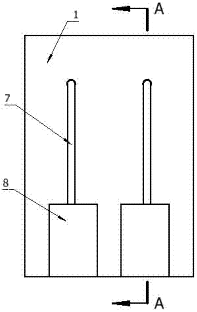
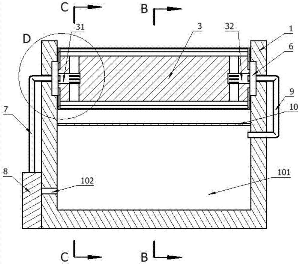
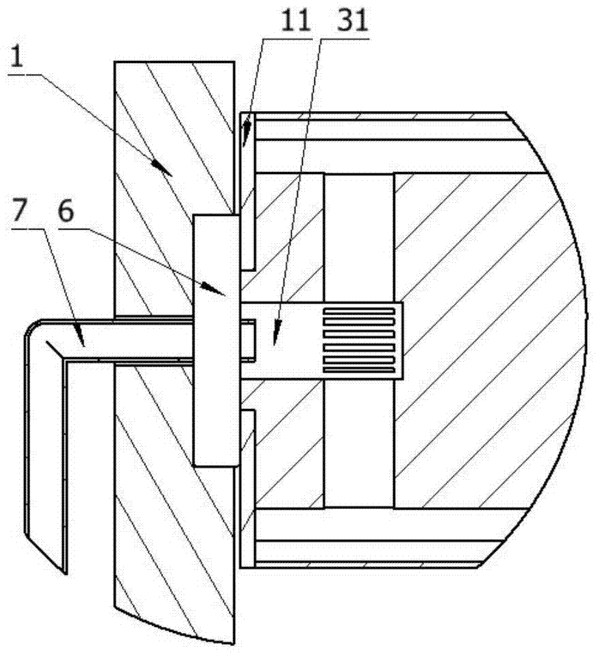
[0025] attached Figure 1-7 It is an intermeshed cooling device for an extruder according to the present invention, which includes a driving shaft 2 and a driven shaft 3 placed horizontally and parallel to each other; the driving shaft 2 and the driven shaft 3 are sleeved with meshing gear sleeves cylinder 4; the driving shaft 2 and the driven shaft 3 are fixedly connected to the gear sleeve 4 through a plurality of support plates 5, and the number of support plates 5 is consistent with the number of teeth of the gear sleeve 4; the adjacent two A water tank 33 is formed between the support plates 5; the two ends of each gear sleeve 4 are respectively provided with sealed end caps 11, and each gear sleeve 4 is fixedly connected with the end caps 11 by welding to prevent water from The two ends of the gear sleeve 4 flow out; one end of...


PUM


Abstract

The invention relates to an engagement cooling apparatus of an extruder. The apparatus comprises a driving shaft and a driven shaft which are horizontal and are arranged in a mutual parallel manner; gear sleeves are sleeved on the driving shaft and the driven shaft respectively; a plurality of water slots are arranged between the driving shaft or the driven shaft and the gear sleeves; one end of each of the driving shaft and the driven shaft is provided with a water inlet hole, and the other end of each of the driving shaft and the driven shaft is provided with a water outlet hole; water inlet holes and water outlet holes are respectively connected with two ends of the water slots; the driving shaft and the driven shaft are correspondingly arranged on a support; the bottom of the support is provided with a water tank; one side of the support close to the water inlet holes is provided with at least one cooling water pump; the cooling water pumps are connected with the water tank through water suction holes; the cooling water pumps are respectively connected with the water inlet holes through water inlet tubes; and each of the water outlet holes is connected with the water tank through a water outlet tube. The apparatus improves the product cooling speed by increasing the extrusion area.

Description

technical field [0001] The invention relates to an engaging cooling device for an extruder. Background technique [0002] In the paint industry, the extruder needs to use a cooler to extrude and cool the viscous and high-temperature semi-finished product during production, and make it into a thin sheet for the next step; and the existing cooler is low in cost due to the wide range of water sources Most of them use water cooling, by setting water tanks parallel to the axis on the inner wall of the driving shaft and the driven shaft, and setting multiple baffles placed at intervals in the water tank, so that the cooling water flows in the driving shaft and the driven shaft. Prolong the residence time of the cooling water in the driving shaft and the driven shaft under the obstruction of the baffle, so that the cooling water and the high-temperature semi-finished product can fully exchange heat; but this method will prolong the cooling water in the driving shaft and the driven ...

Claims


Application Information

Patent Timeline
Patent Type & Authority Applications(China)
IPC IPC(8): B29C43/52
CPCB29C48/9155
Inventor 袁文荣
Owner 苏州普勒新材料有限公司
Why Eureka
Try Eureka