Aircraft

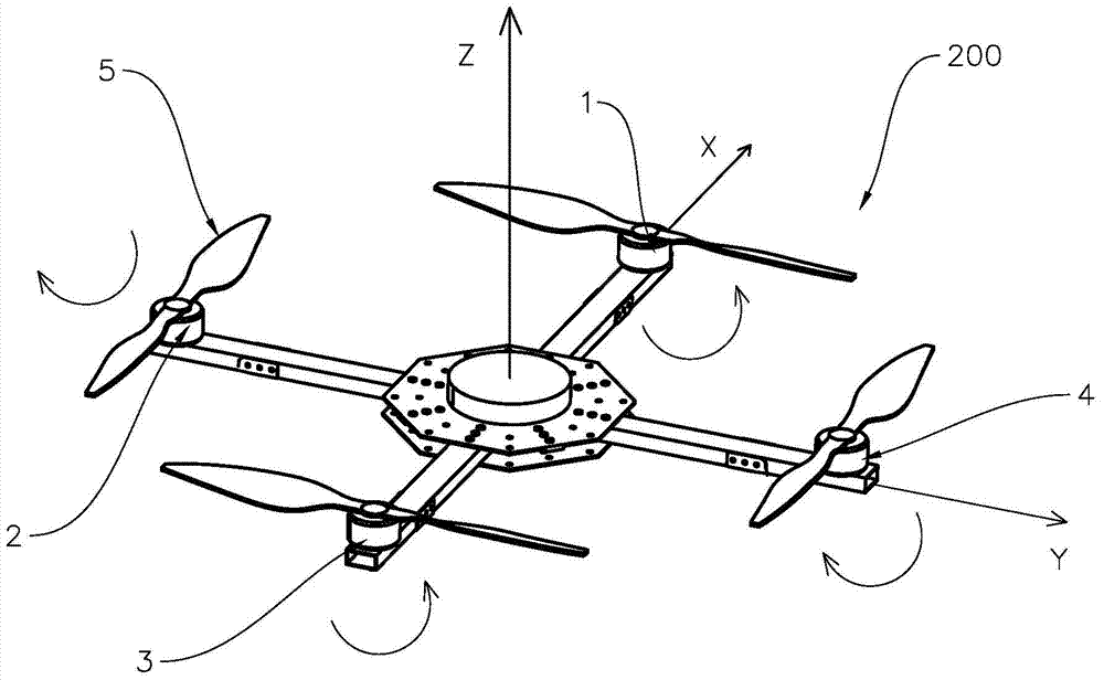
An aircraft and rotor technology, applied in the field of aircraft, can solve problems such as weak stability of aircraft 100, and achieve the effects of improving aerodynamic efficiency, flight flexibility, safety, and optimal flight stability

Active Publication Date: 2015-08-19
ZHUHAI PANLEI INTELLIGENT TECH CO LTD
View PDF8 Cites 11 Cited by
  • Summary
  • Abstract
  • Description
  • Claims
  • Application Information

AI Technical Summary

Problems solved by technology

Just because the rotor 122 of the aircraft 100 needs to be dynamically tilted to balance t

Method used


Image

  • Aircraft
  • Aircraft
  • Aircraft

Examples


no. 1 example

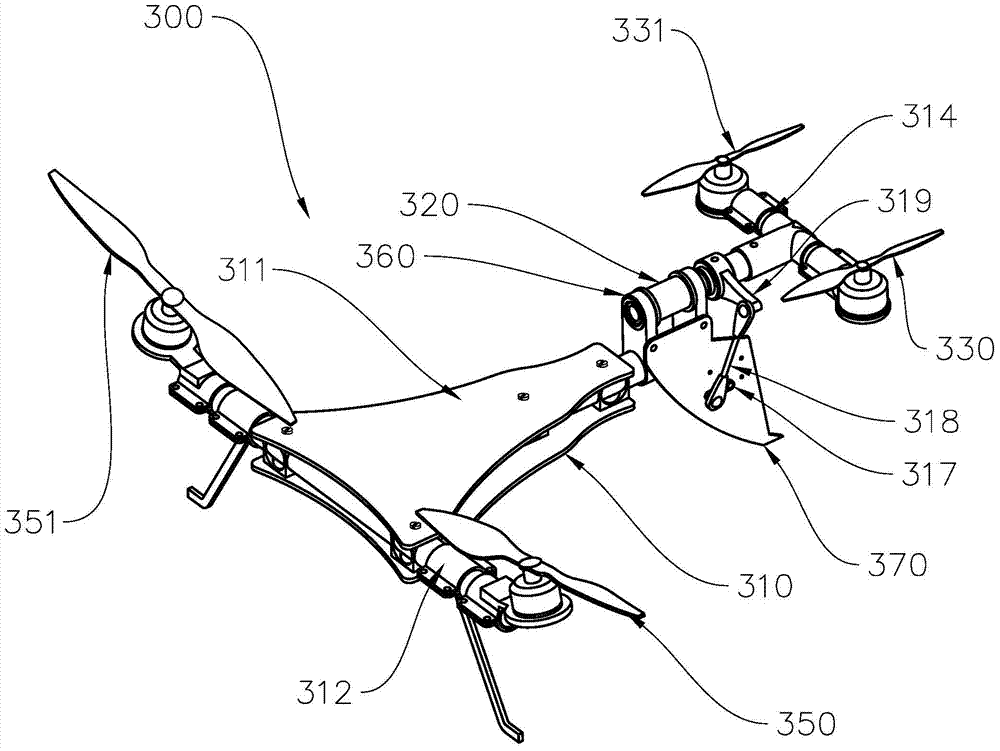
[0044] Such as image 3 , Figure 4 and Figure 5 As shown, the four-axis aircraft 300 of the "T" shape of the present embodiment has a frame 310, and the frame 310 has two triangular pieces 311 arranged in parallel, a first machine arm 314, a first power unit, and a second machine arm. The arm 312 , the second power unit, the fixed connecting rod 313 , the fixed plate 370 as a foot stand, the rotating power unit and the rotating shaft 320 .

[0045] Four penetrating cubic fixing pieces 315 are arranged on the triangular piece 311 . The second power unit has a second rotor device, and the second rotor device has a first sub-rotor 330 and a second sub-rotor 331 . The first power unit has a first rotor device, and the first rotor device has a third sub-rotor 350 and a fourth sub-rotor 351 . Two connecting pieces 360 are fixed on the fixed connecting rod 313 . The rotary power unit has a motor, a crank 317 , a transmission rod 318 , and a rocker arm 319 .

[0046] The secon...

no. 2 example

[0049] Such as Figure 6 As shown, the aircraft 600 has a first power unit, the first power unit has a first rotor device, the first rotor device has a first sub-rotor 610 and a second sub-rotor 620, and the first sub-rotor 610 and the second sub-rotor 620 are The two groups are arranged staggered along the axial direction of the rotating shaft 630 .

no. 3 example

[0051] Such as Figure 7 As shown, the aircraft 700 has a first power unit, the first power unit has a first rotor device, and the first rotor device has a first sub-rotor 710, a second sub-rotor 720 and a fifth sub-rotor 750, wherein the fifth sub-rotor 750 is coaxial with the rotating shaft 730 , and the first sub-rotor 710 and the second sub-rotor 720 are distributed on both sides of the rotating shaft 730 .


PUM


Abstract

The invention belongs to the field of aircrafts, and provides an aircraft. The aircraft comprises a frame, a first power unit, a second power unit and a rotation power unit. The first power unit comprises a first rotor wing device and is mounted on the frame. The second power unit comprises a second rotor wing device and is mounted on the frame rotationally through a rotating shaft. The rotation power unit is mounted on the frame and drives the rotating shaft to rotate. The second rotor wing device comprises a first sub rotor wing and a second sub rotor wing which are distributed on two sides of the rotating shaft. The aircraft has the advantages that horizontal component force of the second rotor wing device is generated only through inclination of the rotating shaft to achieve yawing, inclination of the frame is not needed during yawing, flight resistance is not increased, and flight action flexibility is guaranteed; the first sub rotor wing and the second sub rotor wing are distributed on the two sides of the rotating shaft, larger gas bearing span can be provided for the aircraft without power increase of the second power unit, and accordingly, flight stability of the aircraft is improved.

Description

technical field [0001] The invention belongs to the field of aircraft, in particular to a multi-axis aircraft. Background technique [0002] Usually, the force that drives the aircraft to move upward is called pull force, and the force that drives the aircraft to move horizontally is called thrust. Existing aircraft usually use bladed rotors as pulling rotors to provide pulling force for the aircraft. [0003] The basic flight movements of the aircraft include vertical lift motion, forward and backward motion, lateral motion, pitch motion, roll motion, yaw motion, etc. [0004] see figure 1 , taking the quadrocopter 200 as an example, its four motors are distributed in a cross shape on the X and Y axes perpendicular to each other in the horizontal plane, and the positive direction of the X axis is regarded as the nose direction. Motor 1 is located on the positive half axis of the X axis, motor 3 is located on the negative half axis of the X axis; motor 2 is located on the...

Claims


Application Information

Patent Timeline
IPC IPC(8): B64C27/08B64C27/12B64C27/32
Inventor 何春旺
Owner ZHUHAI PANLEI INTELLIGENT TECH CO LTD
Why Eureka
Try Eureka