Shield-reserved penetration composite type foundation pit support wall and construction method thereof

A foundation pit enclosure and composite technology, which is applied in basic structure engineering, excavation, sheet pile wall, etc., can solve the problems of immature technology, high requirements for excavation equipment, hidden dangers, etc., and achieve mature construction technology, construction quality and safety. Strong risk controllability and effect of reducing impact

Active Publication Date: 2015-08-19
宏润建设集团上海有限公司
View PDF5 Cites 17 Cited by
  • Summary
  • Abstract
  • Description
  • Claims
  • Application Information

AI Technical Summary

Problems solved by technology

The remaining part of the reserved section adopts enclosure structures such as glass fiber reinforced underground diaphragm wall, underground diaphragm wall combined with TRD piles and other construction methods. Due to the lack of such machinery and equipment in the domestic market, the construction period cannot be guaranteed, the technology is immature, and the excavation equipment required in the later stage Higher reasons are difficult to meet the needs of the current project, which has become a technical problem that restricts the progress and quality of the project. Therefore, it is urgent to develop a suitable retaining wall for the underpass of the shield tunnel.
[0004] The existing construction technology, mechanical equipment and technical level of subway deep foundation pit enclosure construction are relatively mature, but some of the new technology and materials are not very mature when encountering the reserved shield tunnel crossing conditions, and lack effective quality control management means , there are usually certain hidden dangers

Method used


Image

  • Shield-reserved penetration composite type foundation pit support wall and construction method thereof
  • Shield-reserved penetration composite type foundation pit support wall and construction method thereof
  • Shield-reserved penetration composite type foundation pit support wall and construction method thereof

Examples


Embodiment Construction

[0028] The present invention will be further described below in conjunction with specific embodiment and accompanying drawing, set forth more details in the following description so as to fully understand the present invention, but the present invention can obviously be implemented in many other ways different from this description, Those skilled in the art can make similar promotions and deductions based on actual application situations without violating the connotation of the present invention, so the content of this specific embodiment should not limit the protection scope of the present invention.

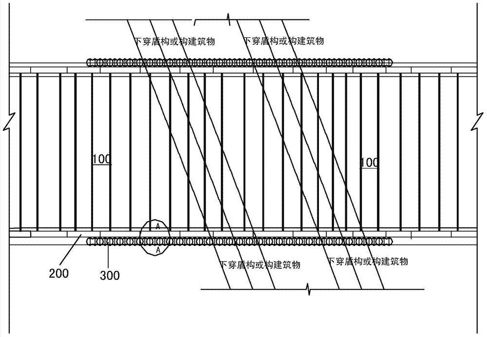
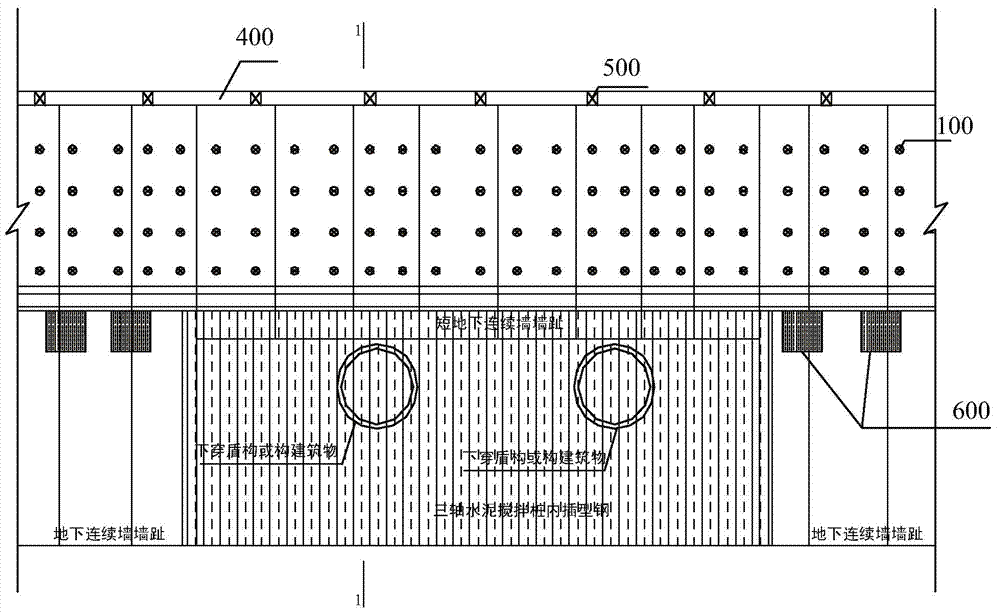
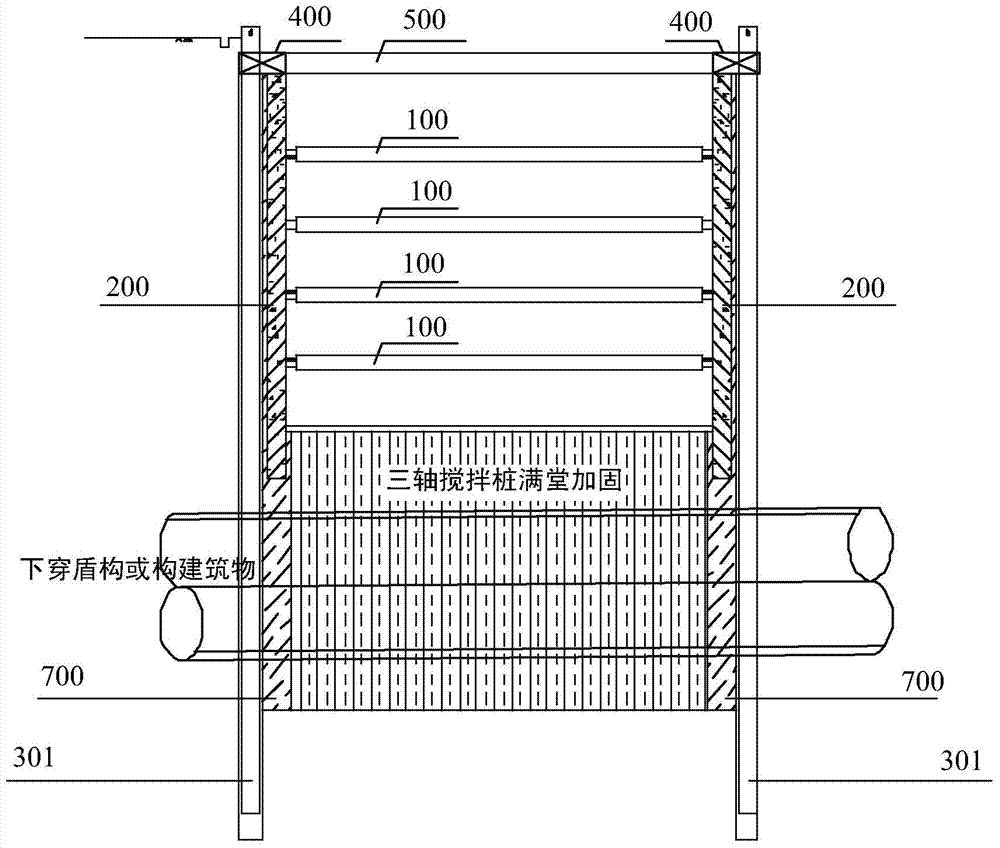
[0029] Such as Figure 1 to Figure 4 , the shield is reserved to pass through the compound foundation pit enclosure wall, including the short underground diaphragm wall 200 and the relatively short underground diaphragm wall 200, which is used to reinforce the underground diaphragm wall (skirt reinforcement). Shaft mixing pile 300 is inserted with section steel 301, and short u...


PUM


Abstract

The invention provides a shield-reserved penetration composite type foundation pit support wall and a construction method of the support wall. The support wall can effectively reduce the influence of construction of rail transit underground engineering in the front period on the later-period shield-reserved excavation construction. In order to solve the technical problem, the shield-reserved penetration composite type foundation pit support wall is characterized by comprising a short underground continuous wall and a stirring pile which is externally placed relative to the short underground continuous wall and used for reinforcing the continuous wall; structural steel is inserted in the stirring pile, and the short underground continuous wall is located above a shield-reserved penetration area; the position between the short underground continuous wall and the stirring pile is filled with a high-pressure rotary spraying pile, and the depth of the high-pressure rotary spraying pile exceeds that of the lower portion of the penetration area and meanwhile exceeds a shallow pressure bearing water layer, and the stirring pile is adopted by the support wall for internal reinforcing; and the position between an internal reinforced part and the short underground continuous wall is filled by a high-pressure rotary spraying pile.

Description

technical field [0001] The invention relates to a retaining wall of a foundation pit and a construction method thereof. Background technique [0002] With the continuous development of urban rail transit engineering construction projects, long-term planning has been made to varying degrees for urban rail transit projects in various places. With the overall development of the city, the network of rail transit projects is constantly increasing and expanding, forming a crisscross network layout. Taking the analysis of cities with relatively advanced and perfect rail transit development, the intersection points of various lines will inevitably have an impact on the later planning, design and construction due to planning issues. [0003] It can be seen that the construction of the reserved section of the foundation pit structure under the shield has gradually become prominent and has become very important. The choice of the conventional enclosure structure often leads to waste o...

Claims


Application Information

Patent Timeline
IPC IPC(8): E02D17/04E02D5/46
Inventor 楼岱许文明葛金明徐乐勇胡宝杰潘林彬
Owner 宏润建设集团上海有限公司
Why Eureka
Try Eureka