High-speed rotating valve and flow parameter real-time detecting device for visualization observation

A technology for real-time detection of flow parameters, applied in fluid pressure actuation devices, valve devices, valve operation/release devices, etc. Effect

Active Publication Date: 2015-08-19
ZHEJIANG UNIV OF TECH
View PDF6 Cites 8 Cited by
  • Summary
  • Abstract
  • Description
  • Claims
  • Application Information

AI Technical Summary

Problems solved by technology

[0003] Aiming at the current problem of inconvenient measurement of flow, pressure, vibration and other parameters in the current observation experiment of internal cavitation of high-speed rotary valves, the present invention proposes a high-speed visual observation and real-time measurement of flow parameters inside the flow field as a starting point, using high-speed camera And synchronous signal measurement (acquisition) technology to realize the structural transformation of the exciter, to improve the excitation performance of the high-speed rotary valve and flow parameter real-time detection device for visual observation

Method used


Image

  • High-speed rotating valve and flow parameter real-time detecting device for visualization observation
  • High-speed rotating valve and flow parameter real-time detecting device for visualization observation
  • High-speed rotating valve and flow parameter real-time detecting device for visualization observation

Examples


Embodiment 1

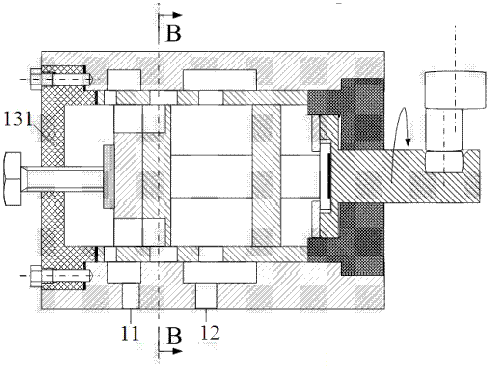
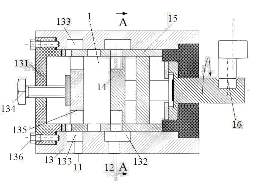
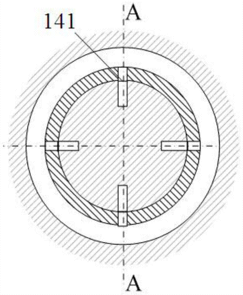
[0030] Embodiment 1 The high-speed rotary valve and flow parameter real-time detection device for visual observation according to the present invention includes a prototype-planar observation valve 1, a high-speed visual observation and analysis device 2, and a flow parameter real-time measurement and signal acquisition device 3. The oil outlet 11 and the oil inlet 12 of the prototype-plane observation valve 1 are respectively connected with the oil inlet and outlet of the oil circuit 4 to form a circuit; the prototype-plane observation valve 1 includes a valve body 13, a valve core 14, and a valve The valve sleeve 15 that the core rotates fits, and the end of the valve body 13 is equipped with a transparent observation window 131; chamber 133, and the first oil chamber 132 communicates with the oil inlet 12, and the second oil chamber 133 communicates with the oil outlet 11; the end of the valve core 14 is connected with the output shaft of the motor 16, and the valve core Th...


PUM


Abstract

A high-speed rotating valve and flow parameter real-time detecting device for visualization observation comprises a prototype-plane observation valve, a high-speed visualization observing and analyzing device and a flow parameter real-time measuring and signal collecting device. The high-speed visualization observing and analyzing device comprises a high-speed video machine and a processor, a camera of the high-speed video machine is aligned with an observation window, the signal output end of the high-speed video machine is connected with the signal input end of the processor, and the signal output end of the processor is connected with the data input end of the flow parameter real-time measuring and signal collecting device. The flow parameter real-time measuring and signal collecting device comprises a signal collecting device and a flow measuring device, wherein the signal input end of the signal collecting device is connected with the corresponding signal output end of the processor, and the signal output end of the signal collecting device is connected with the signal input end of the flow measuring device. The high-speed rotating valve and flow parameter real-time detecting device for visualization observation has the advantages that high-speed / amplification shooting is carried out on the inner air hole flow phenomenon in the rotating valve in a microspur range, and meanwhile flow, vibration, noise and other parameter information data are collected in real time.

Description

technical field [0001] The invention relates to a high-speed rotary valve and a flow parameter real-time detection device for visual observation. Background technique [0002] The key to increasing the excitation frequency of the new electro-hydraulic exciter is to increase the number of grooves on the spool of the high-speed rotary valve or to increase the speed of the spool, which will lead to a decrease in the flow area of ​​the valve port or an increase in the instantaneous flow rate, resulting in a large number of cavitation, not only It will cause flow blockage. At the same time, the pressure pulsation caused by bubble collapse will also form strong nonlinear interference to the system, affecting the frequency output accuracy and stability of the excitation system. In addition, the existing calculation of excitation characteristics is based on the assumption of linearization of characteristic parameters such as flow and pressure in the system. Due to the serious nonlin...

Claims


Application Information

Patent Timeline
Patent Type & Authority Applications(China)
IPC IPC(8): F16K11/085F16K37/00F16K31/04F16K27/06F15B21/04F15B19/00
CPCF15B19/00F15B21/04F16K11/085F16K27/065F16K31/04F16K37/005
Inventor 杜学文邢彤彭金华
Owner ZHEJIANG UNIV OF TECH
Why Eureka
Try Eureka