Movable hot blast heater

A hot stove, mobile technology, applied in the direction of air heaters, fluid heaters, lighting and heating equipment, etc., can solve problems such as trouble, hot stove can not be moved, labor intensity, etc., to achieve the effect of convenient use

Active Publication Date: 2015-08-19
ANHUI KECHANG MACHINERY MFG
5 Cites 1 Cited by

AI-Extracted Technical Summary

Problems solved by technology

[0002] With long-term practice, people have realized that using hot air as a medium and carrier can greatly improve heat utilization rate and thermal work effect, so hot air stoves have been widely used in the fields of architectural paint drying, cement maintenance, etc. The hot blast stove cannot be moved, especial...

Method used

The present invention is implemented like this: coal block is put into on metal grid 7 by coal filling mouth 8, ignites and burns, and flame and hot gas enter heat pipe 12 and heat pipe 12 is heated, and cold air blower 14 will The cold air blows into the heating chamber 10 through the air inlet pipe 13, the air in the heating chamber 10 is in contact with the heat conduction pipe 12 and is heated by the heat conduction pipe 12, the heated hot air is output from the air outlet pipe 15, and the coal slag is removed from the slag removal port 9 , since the front and rear ends of the base 1 are respectively equipped with a roller 2 through bearings, and a roller 3 is fixed at both ends of the roller 2, so that the staff only needs to push the base 1 throug...

Abstract

The invention discloses a movable hot blast heater which comprises a base, rollers, wheels, a rotating shaft, a rotating disc, a combustion bin, metal grids, a coal filling opening, a slag removal opening, a heating bin, a smoke discharge pipe, a heat conduction pipe, an air inlet pipe, a cold air blower, an air outlet pipe, a rotating sleeve, a wood handle and a handle. The front end and the rear end of the base are provided with the rollers through bearings respectively. The two ends of each roller are each fixedly provided with one wheel. The rotating shaft is vertically installed on the base through a bearing. The rotating disc is welded to the upper end of the rotating shaft. The combustion bin is welded to the rotating plate. The coal filling opening is welded to the upper portion of the combustion bin. The slag removal opening is welded to the lower portion of the combustion bin. The heating bin is welded to the upper portion of the combustion bin. The upper end of the heat conduction pipe is connected with the lower end of the smoke discharge pipe through welding. The cold air blower is connected with the air inlet pipe through a hose. The air outlet pipe is welded to the lower portion of the heating bin. The movable hot blast heater has the advantages of being convenient to use, capable of saving labor and time and the like.

Application Domain

Air heaters

Technology Topic

Metal gridSlag +7

Image

  • Movable hot blast heater

Examples

  • Experimental program(1)

Example Embodiment

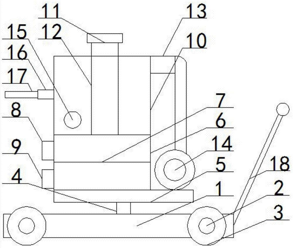
[0010] Such as figure 1 As shown, the present invention discloses a mobile hot blast stove, including: base 1, roller 2, roller 3, rotating shaft 4, turntable 5, combustion bin 6, metal grid 7, coal filling port 8, and slag removal port 9. , Heating chamber 10, exhaust pipe 11, heat conduction pipe 12, air inlet pipe 13, cold air blower 14, air outlet pipe 15, rotating sleeve 16, wooden handle 17, handle 18, the front and rear ends of the base 1 pass The bearings are respectively mounted with a roller 2, two ends of the roller 2 are respectively fixed with a roller 3, the rotating shaft 4 is vertically mounted on the base 1 through the bearing, and the turntable 5 is welded to the upper end of the rotating shaft 4. , The combustion bin 6 is welded to the turntable 4, the inside of the combustion bin 6 is welded horizontally with a metal grid 7, the coal filling port 8 is welded to the upper part of the combustion bin 6, and the coal filling port 8 The position is at the upper part of the metal grid 7, the slag removal port 9 is welded to the lower part of the combustion chamber 6, and the location of the slag removal port 9 is at the lower part of the metal grid 7, and the heating chamber 10 is welded to the combustion chamber 6. The upper part of the said exhaust pipe 11 is welded to the upper part of the heating chamber 10, the lower end of the said heat conduction pipe 12 is connected to the combustion chamber 6 by welding, and the inside of the heat conduction pipe 12 communicates with the inside of the combustion chamber 6, so The upper end of the heat pipe 12 and the lower end of the exhaust pipe 11 are connected by welding, the air inlet pipe 13 is welded to the upper end of the heating chamber 10, and the cold air blower 14 is installed on the turntable 4 by bolts, The cold air blower 14 is connected to the air inlet pipe 15 through a hose, the air outlet pipe 15 is welded to the lower part of the heating chamber 10, and the rotating sleeve 16 is welded to the circumferential surface of the heating chamber 10. One end of the wooden handle 17 is inserted into the rotating sleeve 16, and the handle 18 is welded to the front end of the base 1.
[0011] The present invention is implemented as follows: the coal block is put into the metal grid 7 through the coal filling port 8 and ignited for combustion. The flame and hot air enter the heat transfer pipe 12 and heat the heat transfer pipe 12, and the cold air blower 14 passes the cold air through the inlet The air pipe 13 is blown into the heating chamber 10, the air in the heating chamber 10 contacts the heat conduction pipe 12 and is heated by the heat conduction pipe 12. The heated hot air is output from the air outlet pipe 15, and the cinder is removed from the slag removal port 9. A roller 2 is installed at the front and rear ends of 1 through a bearing, and a roller 3 is fixed at both ends of the roller 2, so that the staff only needs to push the base 1 through the handle 19, so that the staff can easily move the whole to Where the wall paint needs to be dried, since the rotating shaft 4 is vertically mounted on the base 1 through bearings, the rotating disk 5 is welded to the upper end of the rotating shaft 4, and the combustion chamber 6 is welded to the rotating disk 4, so that the rotating shaft 4 can rotate, the rotating disk 5 It can also be turned. The staff only needs to turn the rotating sleeve 16 through the wooden handle 17 and then drive the heating chamber 10 and the combustion chamber 6 to rotate until the air outlet pipe 15 is aligned with the wall to be dried. It is more convenient to use and very Great savings in manpower, labor intensity is also significantly reduced, saving labor and time.
[0012] Finally, it should be noted that the above embodiments are only used to illustrate the present invention and not to limit the technical solutions described in the present invention; therefore, although this specification has described the present invention in detail with reference to the above embodiments, the field Those of ordinary skill should understand that the present invention can still be modified or equivalently replaced; and all technical solutions and improvements that do not depart from the spirit and scope of the present invention should be covered in the scope of the claims of the present invention.

PUM

no PUM

Description & Claims & Application Information

We can also present the details of the Description, Claims and Application information to help users get a comprehensive understanding of the technical details of the patent, such as background art, summary of invention, brief description of drawings, description of embodiments, and other original content. On the other hand, users can also determine the specific scope of protection of the technology through the list of claims; as well as understand the changes in the life cycle of the technology with the presentation of the patent timeline. Login to view more.

Similar technology patents

Household appliance control method and device and mobile terminal

InactiveCN103605531Aeasy to operateeasy to use
Owner:GD MIDEA AIR-CONDITIONING EQUIP CO LTD +1

Multi-stage oral-fluid testing device

ActiveUS20160121322A1easy to use
Owner:PREMIER BIOTECH LLC

System and method of monitoring temperature

InactiveUS7140768B2less susceptible to tampereasy to use
Owner:COLD CHAIN TECH

Wireless charging transmitter, receiver, charging device and wireless charging method

ActiveCN104158269ASimple codingeasy to use
Owner:湖南长城科技信息有限公司 +1

Classification and recommendation of technical efficacy words

  • easy to use

Laser assisted total joint arthroplasty

InactiveUS20090234360A1easy to use
Owner:ALEXANDER VLADIMIR

Enclosure for a portable hemodialysis system

ActiveUS20090114582A1easy to use
Owner:DEKA PROD LLP
Why Eureka
Try Eureka