
Stewart platform attitude measurement device and measurement method

A technology for measuring devices and platforms, which is applied to measuring devices, navigation through velocity/acceleration measurement, instruments, etc., can solve the problems of inability to determine the direction of angular velocity, unsuitable sensors for applications, accumulation of angular velocity errors, etc., so as to facilitate the measurement of Stewart platform attitude , the effect of fast calculation and fast response

Active Publication Date: 2017-06-09
GENERAL ENG RES INST CHINA ACAD OF ENG PHYSICS
View PDF4 Cites 0 Cited by
  • Summary
  • Abstract
  • Description
  • Claims
  • Application Information

AI Technical Summary

Problems solved by technology

Some of the main disadvantages are that the direction of the angular velocity cannot be determined because the angular velocity item is calculated by the square root; or the amount of calculation is large, and the error of the angular velocity accumulates with time, or the accuracy of the installation is too high, and the practical application is difficult. Due to the above reasons, the six accelerometer method not ideal way
The nine-accelerometer configuration scheme is an improved method. The redundant information output by the accelerometer is used to improve the angular velocity calculation algorithm to improve accuracy. The angular velocity sign is determined by the angular acceleration integral to eliminate the uncertainty of the angular velocity sign, and the square root of the angular velocity Determine the value to suppress the iterative error, but the specific algorithm is in the publication, and from the literature, the installation position configuration of the sensor is not suitable for use on a moving platform such as Stewart

Method used


Image

  • Stewart platform attitude measurement device and measurement method
  • Stewart platform attitude measurement device and measurement method
  • Stewart platform attitude measurement device and measurement method

Examples


Embodiment Construction

[0034] The present invention will be further described below in conjunction with accompanying drawing:

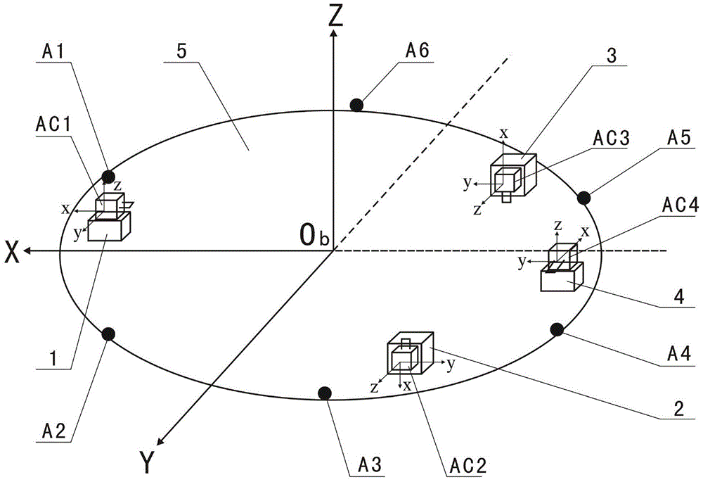
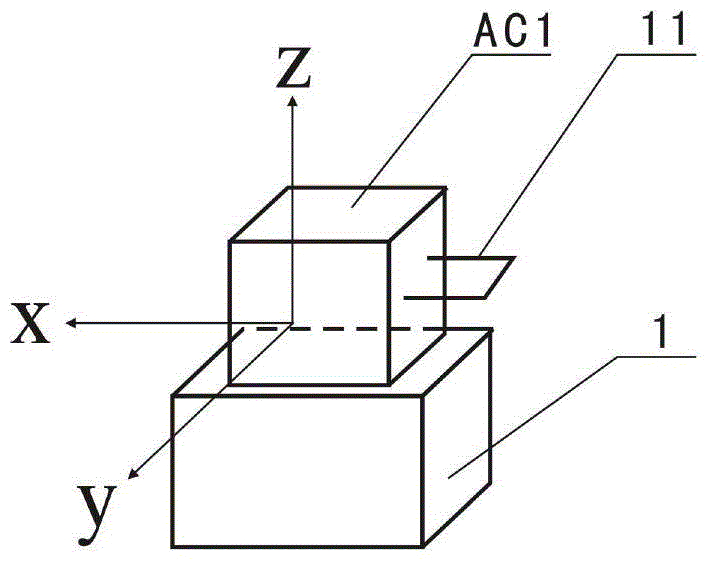
[0035] Such as figure 1 and figure 2 As shown, the Stewart platform of the present invention includes a dynamic platform 5 and a static platform (has nothing to do with the innovative solution of the present invention, so it is not shown in the figure), and the dynamic platform 5 and the static platform are respectively connected with six movable platforms by six spherical joints. Telescopic connecting rods (not shown in the figure) are connected, and the six spherical joints of the moving platform 5 are respectively the first spherical joint A1, the second spherical joint A2, the third spherical joint A3, the fourth spherical joint A4, and the fifth spherical joint. Hinge A5, the sixth spherical joint A6; Stewart platform attitude measurement device of the present invention comprises four three-axis acceleration sensors, namely the first three-axis acceleration sensor AC...


PUM


Abstract

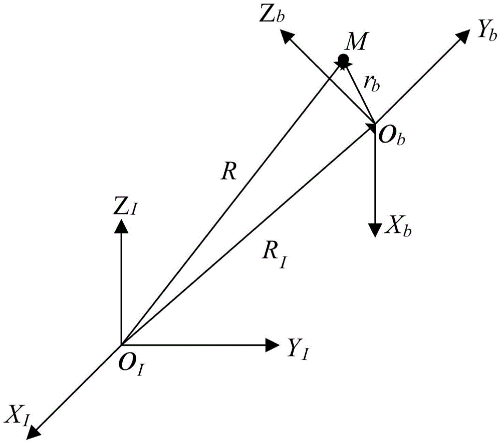
The invention discloses a Stewart platform attitude measurement device. Axial directions of three coordinate axes of a movable platform coordinate system are respectively X, Y and Z, four tri-axial acceleration sensors are installed on the movable platform of the Stewart platform through four cushion blocks, two tri-axial acceleration sensors are symmetric to each other by using a coordinate origin Ob of the movable platform coordinate system and respectively arranged at two sides of the X axis, another two tri-axial acceleration sensors are symmetrically installed by using the X axis as the symmetric axis. The invention further discloses a measurement method adopted by the Stewart platform attitude measurement device, the acceleration component of the coordinate origin Ob of the movable platform with respect to the coordinate origin OI of a fixed platform and a movable platform rotation angle speed are obtained through a formula, so that the position and attitude parameters of the movable platform coordinate system with respect to the fixed platform coordinate system can be obtained. Through the adoption of the measurement device and measurement method disclosed by the invention, the centroid coordinate, the rotation angle and the rotation direction parameter of the Stewart platform can be directly obtained without complex computation.

Description

technical field [0001] The present invention relates to a Stewart platform attitude measurement device and measurement method, in particular to a measurement device and measurement method that uses a full acceleration sensor to measure the attitude parameters of the six-degree-of-freedom Stewart platform centroid position, rotation angle and rotation direction, and belongs to sports Simulator pose measurement field. Background technique [0002] The Stewart platform is also called the parallel platform mechanism, which is composed of a dynamic platform, a static platform, a hinge and six driving rods, and can realize rotation in 6 degrees of freedom. Because this mechanism has the advantages of simple structure, good dynamic performance, high rigidity, and strong bearing capacity, it is widely used in robots, machine tool manufacturing industries, automobile motion simulators, aerospace vehicle simulators, space docking mechanisms, submarine rescue docking devices and high-s...

Claims


Application Information

Patent Timeline
Patent Type & Authority Patents(China)
IPC IPC(8): G01B21/00G01C21/16
CPCG01C21/16
Inventor 张毅张荣周继昆陈颖
Owner GENERAL ENG RES INST CHINA ACAD OF ENG PHYSICS
Learn More