Dynamic performance testing machine of joint bearing and transmission shaft rotation drive unit thereof

A dynamic performance and joint bearing technology, applied in the direction of mechanical bearing testing, etc., can solve the problem of large shock and vibration of the driving mechanism, achieve the effects of small shock and vibration, reduce the overall size, and reduce power requirements

Active Publication Date: 2015-08-19
台州科锦轴承有限公司
View PDF7 Cites 6 Cited by
  • Summary
  • Abstract
  • Description
  • Claims
  • Application Information

AI Technical Summary

Problems solved by technology

[0005] The invention provides a transmission shaft rotation drive device for a joint bearing dynamic performance testing machine to solve the technical problem in the prior art that the driving mechanism that uses a slider to drive the active pendulum to swing has a relatively large impact and vibration; at the same time, the invention also provides Provided is a dynamic performance testing machine for joint bearings using the above transmission shaft rotation drive device

Method used


Image

  • Dynamic performance testing machine of joint bearing and transmission shaft rotation drive unit thereof
  • Dynamic performance testing machine of joint bearing and transmission shaft rotation drive unit thereof
  • Dynamic performance testing machine of joint bearing and transmission shaft rotation drive unit thereof

Examples


Embodiment Construction

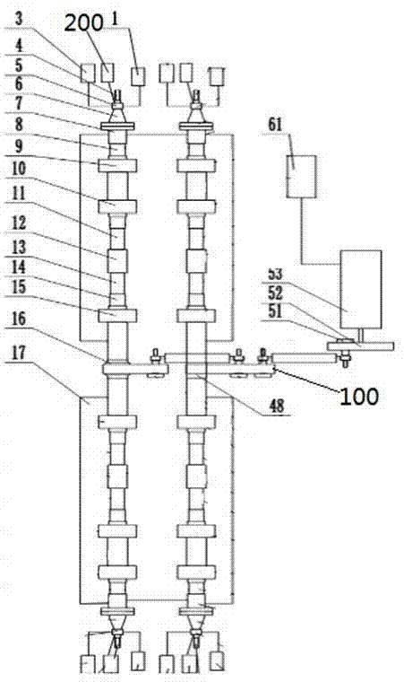
[0023] like Figure 1 to Figure 3 As shown, an embodiment of a dynamic performance testing machine for a joint bearing, the testing machine in this embodiment is a rod end joint bearing testing machine for testing a rod end joint bearing, and the testing machine includes two parallel arrangement The transmission shaft 14 used to drive the inner ring of the rod end joint bearing to be tested to rotate, the two transmission shafts 14 are axial transmission shafts coaxially arranged with the inner ring of the corresponding rod end joint bearing to be tested respectively, and the two transmission shafts 14 A rod end joint bearing is respectively provided at both ends, and when the two transmission shafts are driven to rotate synchronously by the transmission shaft rotation driving device 100, the inner ring of the rod end joint bearing to be tested can be driven to rotate.

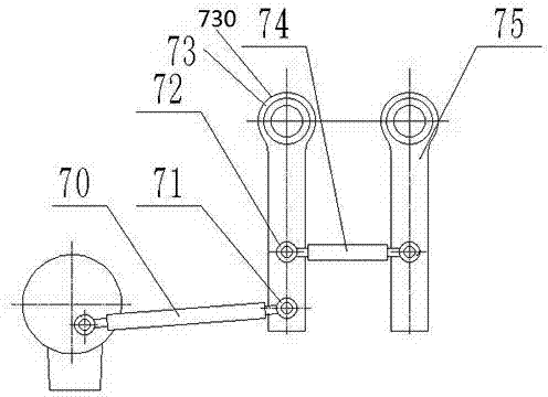
[0024] The transmission shaft rotation driving device 100 in this embodiment includes a parallel linkage me...


PUM


Abstract

The invention provides a dynamic performance testing machine of a joint bearing and a transmission shaft rotation drive unit thereof. The testing machine comprises at least two transmission shafts that are arranged in parallel and are used for driving an inner ring or outer ring of a to-be-tested bearing; and the transmission shafts are driven by a transmission shaft rotation drive unit to make synchronous rotation. The transmission shaft rotation drive unit includes a parallel connecting rod structure. The parallel connecting rod structure contains a plurality of drive oscillating rods that extend in parallel and are fixedly connected with the transmission shafts in a one-to-one correspondence mode and transmission connecting rods hinged between the adjacent drive oscillating rods; and one drive oscillating rod serves as a driving oscillating rod driven by a power mechanism. The power mechanism consists of a drive motor and a driving crank in transmission connection with a power output shaft of the drive motor; and the driving crank uses a drive connecting rod to drive the driving oscillating rod to make oscillation. One end of the drive connecting rod is hinged with the driving crank and the other end is hinged with the driving oscillating rod. The driving crank, the driving oscillating rod, and the driving oscillating rod form a crank rod-oscillating mechanism. The structure is simple, the impact vibration is low, and the noises are low.

Description

technical field [0001] The invention relates to a joint bearing dynamic performance testing machine and a transmission shaft rotation driving device thereof. Background technique [0002] The joint bearing is a spherical sliding friction swing bearing, which is mainly composed of an inner ring with an outer spherical surface and an outer ring with an inner spherical surface. Joint bearings are widely used and have a high degree of standardization. According to whether there is a rod end (or whether it is installed on the rod end), the joint bearing can be divided into: general joint bearing and rod end joint bearing. With the continuous improvement of the industrial level, rod ends are widely used in mechanical equipment in aviation, textile, coal mine and other industries. At the same time, the equipment manufacturing industry has higher and higher requirements for the quality of rod ends, and the evaluation standards The requirements are becoming more and more string...

Claims


Application Information

Patent Timeline
Patent Type & Authority Applications(China)
IPC IPC(8): G01M13/04
Inventor 占松华赵银龙徐煜星张平
Owner 台州科锦轴承有限公司
Why Eureka
Try Eureka