
igbt state detection circuit and igbt state detection method

A state detection and circuit technology, applied in the direction of measuring electricity, measuring electrical variables, measuring devices, etc., can solve problems such as inaccurate judgment, long time delay, poor applicability, etc., reduce special requirements for model selection, and prevent overvoltage hazards , good effect of circuit versatility

Active Publication Date: 2018-02-23
BEIQI FOTON MOTOR CO LTD
View PDF6 Cites 2 Cited by
  • Summary
  • Abstract
  • Description
  • Claims
  • Application Information

AI Technical Summary

Problems solved by technology

[0003] The existing IGBT state detection has the following methods: (1) using an integrated drive module, but this detection module detects the IGBT driver level signal, which can only be detected when the IGBT is turned on, and the price is high and the applicability is poor; (2) using Zener tube plus series optocoupler mode, but this detection mode can only detect the situation that the voltage between C and E is higher than the driving power supply voltage when the IGBT is short-circuited. If the voltage between C and E is lower than the driving power supply voltage, it cannot be accurately judged , and there is a large delay, which cannot realize real-time monitoring
That is, there is a lack of a circuit and method that can detect the state of the IGBT in real time, effectively, accurately and reliably in the prior art

Method used


Image

  • igbt state detection circuit and igbt state detection method
  • igbt state detection circuit and igbt state detection method

Examples


Embodiment Construction

[0021] Specific embodiments of the present invention will be described in detail below in conjunction with the accompanying drawings. It should be understood that the specific embodiments described here are only used to illustrate and explain the present invention, and are not intended to limit the present invention.

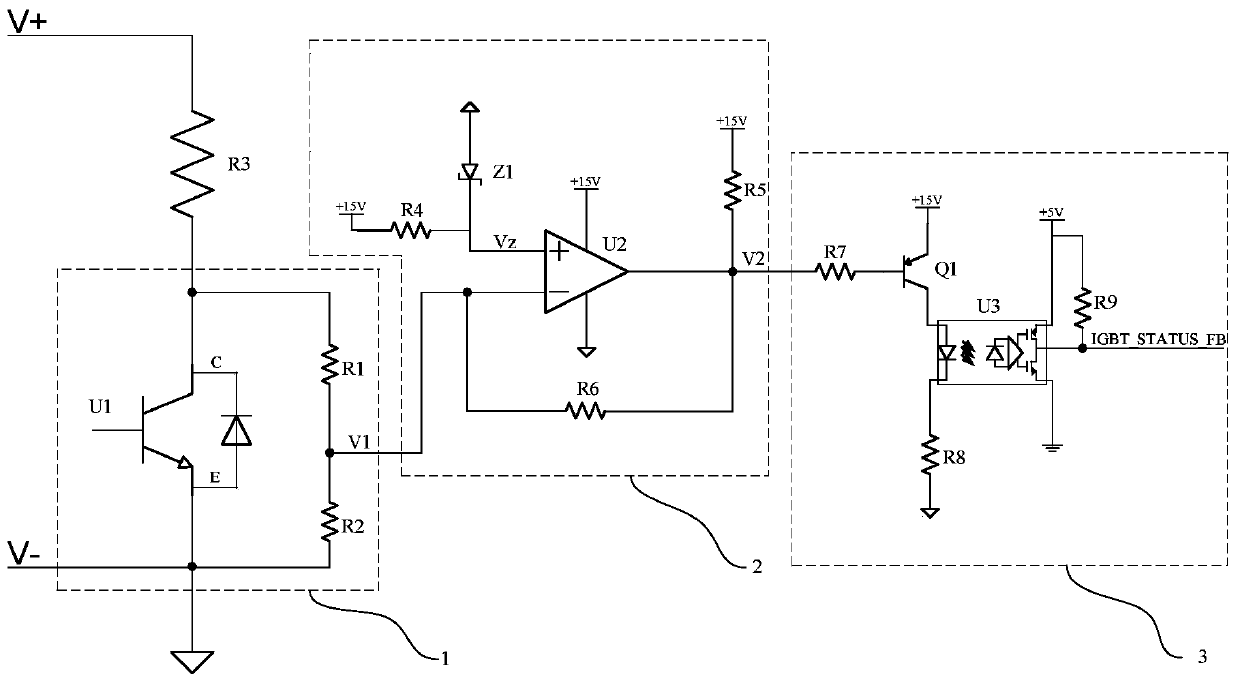
[0022] In order to clarify the idea of ​​the present invention more clearly, the circuit diagram of an example IGBT state detection circuit will be described in detail below. figure 1 is a circuit diagram of an example IGBT state detection circuit according to an embodiment of the present invention, as figure 1 As shown, the circuit includes: a parallel voltage divider circuit 1 between the collector and the emitter of the IGBT, which is used to obtain the divided voltage of the voltage between the collector and the emitter of the IGBT and output the divided voltage signal V1 to the voltage comparison The input end of the circuit 2; the voltage comparison circu...


PUM


Abstract

The invention discloses an IGBT state detecting circuit and an IGBT state detecting method. The IGBT state detecting circuit includes a parallel bleeder circuit (1) arranged between a collector and an emitter of an IGBT and used for acquiring bleeding voltage of the voltage between the collector and the emitter of the IGBT and outputting bleeding voltage signals (V1) to the input terminal of a voltage comparing circuit (2); the voltage comparing circuit (2) used for judging the state of the IGBT according to the bleeding voltage signals (V1) and a predetermined voltage signal (Vz) and outputting IGBT state feedback signals (V2) to the input terminal of a state feedback isolation output circuit (3); the state feedback isolation output circuit (3) used for outputting IGBT state feedback isolation signal in response to the IGBT state feedback signals (V2). The IGBT state detecting circuit and the IGBT state detecting method provided by the invention can be used for real time, effective, accurate and reliable detection of IGBT state.

Description

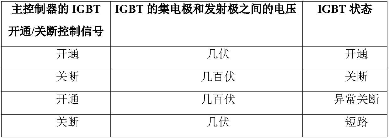
technical field [0001] The invention relates to the field of automobiles, in particular to an IGBT state detection circuit and an IGBT state detection method. Background technique [0002] In the prior art, in order to protect the power devices of the main circuit in the main controller of the electric vehicle motor, an active discharge circuit is usually set up. Usually, the active discharge circuit is composed of a discharge resistor and an insulated gate bipolar transistor (IGBT), and is connected between the positive and negative poles of the DC bus voltage. Generally, the working state of the IGBT mainly includes: on, off, and short circuit. In order to protect the main circuit power devices in the main controller and improve the safety of electric vehicles, it is necessary to detect the working status of the IGBT. [0003] The existing IGBT state detection has the following methods: (1) using an integrated drive module, but this detection module detects the IGBT driv...

Claims


Application Information

Patent Timeline
Patent Type & Authority Patents(China)
IPC IPC(8): G01R31/27
Inventor 王晓辉王野
Owner BEIQI FOTON MOTOR CO LTD
Learn More