Gradient coil for nuclear magnetic resonance spectrometer

A technology of nuclear magnetic resonance spectroscopy and gradient coils, applied to instruments, measuring magnetic variables, measuring devices, etc., can solve the problems of increasing coil inductance and resistance, limited space of gradient coils, and affecting the switching speed of gradient fields of coils, etc. Small inductance and resistance, ensuring stability, solving the effect of deformation

Active Publication Date: 2015-08-19
ウーハン ジョンケ ニウジン マグネティック レゾナンス テクノロジー カンパニー リミテッド
View PDF7 Cites 7 Cited by
  • Summary
  • Abstract
  • Description
  • Claims
  • Application Information

AI Technical Summary

Problems solved by technology

Therefore, it is necessary to add a gradient coil to the NMR spectrometer probe, which generates a gradient field driven by an external pulse gradient current. The stronger the gradient field, the better. However, when the gradient coil generates a gradient field, the metal conductor near it The stronger the gradient field, the easier it is to generate eddy current. The eddy current will generate a magnetic field opposite to the original gradient field, which will reduce the efficiency of the gradient coil and the stability of the magnetic field, which will affect the normal operation of the NMR spectrometer.
[0003] In the prior art, the method of flow function and target field is used to solve the problem. However, the space for placing the gradient coil in the NMR spectrometer probe is very limited. The gradient coil must meet the requirements of small size, small inductance, and strong gradient field. When the field method requires high field strength and the coil volume is strictly limited, it is difficult to obtain a reasonable gradient coil scheme by this design method, and it leads to processing difficulties and cannot be used for actual production
[0004] At present, there is a mainstream method of using self-shielding coils to solve the eddy current problem, but the shielding coil will generate a reverse magnetic field in the target area, which will cancel almost half of the gradient field of the main coil, so in order to obtain a strong enough gradient field, it has to be increased The number of coil windings, but in the case of increasing the number of windings, the inductance and resistance of the coil are increased, which affects the gradient field switching speed of the coil and significantly increases the power consumption of the coil

Method used


Image

  • Gradient coil for nuclear magnetic resonance spectrometer
  • Gradient coil for nuclear magnetic resonance spectrometer
  • Gradient coil for nuclear magnetic resonance spectrometer

Examples


Embodiment Construction

[0026] In order to make the object, technical solution and advantages of the present invention more clear, the present invention will be further described in detail below in conjunction with the accompanying drawings and embodiments. It should be understood that the specific embodiments described here are only used to explain the present invention, not to limit the present invention. In addition, the technical features involved in the various embodiments of the present invention described below can be combined with each other as long as they do not constitute a conflict with each other.

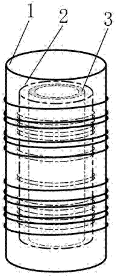
[0027] The gradient coil of the present invention is made up of shielding coil 1, main coil 2 and quartz glass tube 3, as figure 1 A schematic diagram of the overall structure of the gradient coil of the NMR spectrometer shown. The shielding coil 1 is placed on the outer layer of the main coil 2 with a distance of 4.3-5.3 mm between them. The magnetic field generated by the shielding coil 1 ...


PUM


Abstract

The invention discloses a gradient coil for a nuclear magnetic resonance spectrometer, and the gradient coil consists of main coils and shielding coils, wherein the shielding coils are coaxially disposed at an outer side of the main coils. The main coils are a plurality of groups of coil windings which are symmetrically distributed at the upper and lower parts in the axial direction of the coil. The upper two groups of coils and the lower two groups of coils are in opposite winding directions. The shielding coils are two groups of coil windings which are symmetrically distributed at the upper and lower parts and are in opposite winding direction. All the winding coils are in series connection. An interval from 4.3 mm to 5.3 mm is kept between the shielding coils and the main coils, and the interior of the main coils is provided with a thermal isolation part. According to the invention, the coil remarkably improves the coil efficiency, and a gradient magnetic field can be obtained through the simple algorithm and technology, wherein the intensity of the gradient magnetic field is greater than 50 Gs/cm@10A, and the linear error is less than 0.5 Gs/cm@10A. Moreover, the coil can guarantee the stability of a gradient field in a variable temperature experiment.

Description

technical field [0001] The invention belongs to the field of nuclear magnetic resonance spectrometers, and more specifically relates to a gradient coil. Background technique [0002] When the NMR spectrometer performs gradient shimming and two-dimensional gradient experiments, a strong longitudinal gradient field needs to be generated in the main magnetic field, and its strength is generally required to be above 50Gs / cm10A. Therefore, it is necessary to add a gradient coil to the NMR spectrometer probe, which generates a gradient field driven by an external pulse gradient current. The stronger the gradient field, the better. However, when the gradient coil generates a gradient field, the metal conductor near it The stronger the gradient field, the easier it is to generate eddy current. The eddy current will generate a magnetic field opposite to the original gradient field, which will reduce the efficiency of the gradient coil and the stability of the magnetic field, affectin...

Claims


Application Information

Patent Timeline
Patent Type & Authority Applications(China)
IPC IPC(8): G01R33/385
Inventor 陈康
Owner ウーハン ジョンケ ニウジン マグネティック レゾナンス テクノロジー カンパニー リミテッド
Why Eureka
Try Eureka