
A High Torque Density Modulated Magnetic Gear

A magnetic field modulation and magnetic gear technology, which is applied to permanent magnet clutches/brakes, electric brakes/clutches, electromechanical devices, etc., can solve the problems of high processing technology requirements, complex processing and assembly, and large amount of permanent magnets. High-temperature demagnetization, less harmonic content, and increased air-gap working flux density

Active Publication Date: 2018-11-02
HUAZHONG UNIV OF SCI & TECH
View PDF8 Cites 0 Cited by
  • Summary
  • Abstract
  • Description
  • Claims
  • Application Information

AI Technical Summary

Problems solved by technology

[0003] With the deepening of the research on magnetic field modulation magnetic gears, various magnetic gears with different structures have been developed one after another; such as axial disc magnetic gears, tangentially polarized magnetic gears, Halbach magnetic gears, and three-layer permanent magnet magnetic gears; These structures have high torque density, but there are also defects: large torque fluctuation, complex shape, large amount of permanent magnets, high requirements for processing technology, etc.
In 2014, K.K.Uppalapati et al. proposed a high torque density magnetic gear structure (K.K.Uppalapati, J.Z.Bird, J.Wright, J.Pitchard. A Magnetic Gearbox with an Active Region Torque Density of 239Nm / L. Energy Conversion Congress and Exposition (ECCE), IEEE.pp.1422-1428.2014), the permanent magnets of the inner and outer rotors are tangentially polarized, using the magnetic field concentration effect of tangential polarization, a higher torque density can be achieved, but the torque fluctuation Larger and more complicated to process and assemble

Method used


Image

  • A High Torque Density Modulated Magnetic Gear
  • A High Torque Density Modulated Magnetic Gear
  • A High Torque Density Modulated Magnetic Gear

Examples


Embodiment Construction

[0027] In order to make the object, technical solution and advantages of the present invention clearer, the present invention will be further described in detail below in conjunction with the accompanying drawings and embodiments. It should be understood that the specific embodiments described here are only used to explain the present invention, not to limit the present invention. In addition, the technical features involved in the various embodiments of the present invention described below can be combined with each other as long as they do not constitute a conflict with each other.

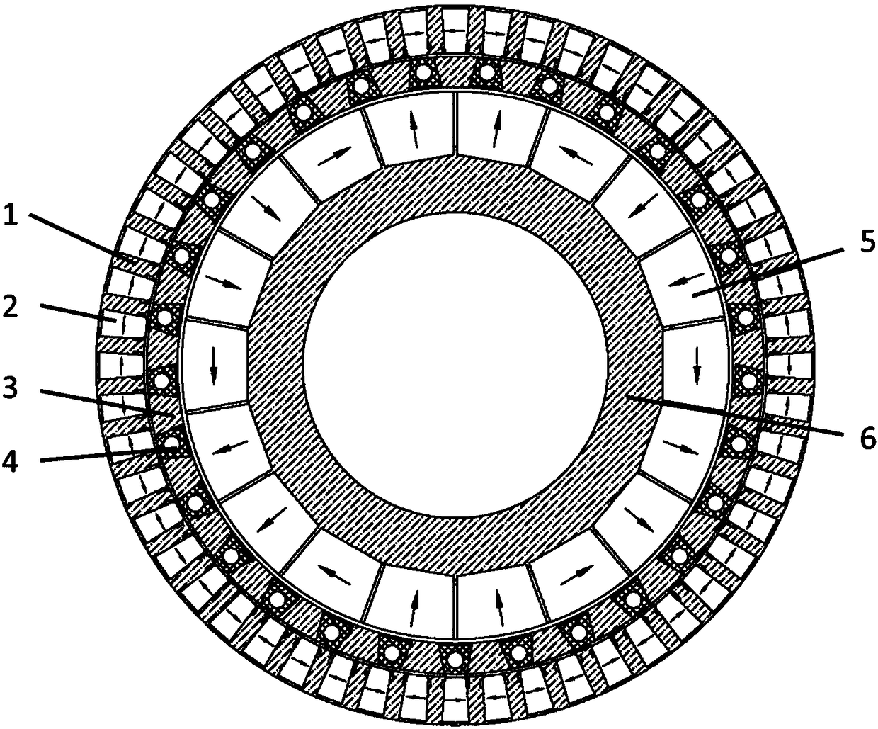
[0028] figure 1 Shown is a schematic structural diagram of a high torque density magnetic field modulation type magnetic gear provided by an embodiment of the present invention; the magnetic field modulation type magnetic gear of the embodiment includes a permanent magnet outer stator, a modulating rotor and a permanent magnet inner rotor; the permanent magnet outer stator , The modulation roto...


PUM


Abstract

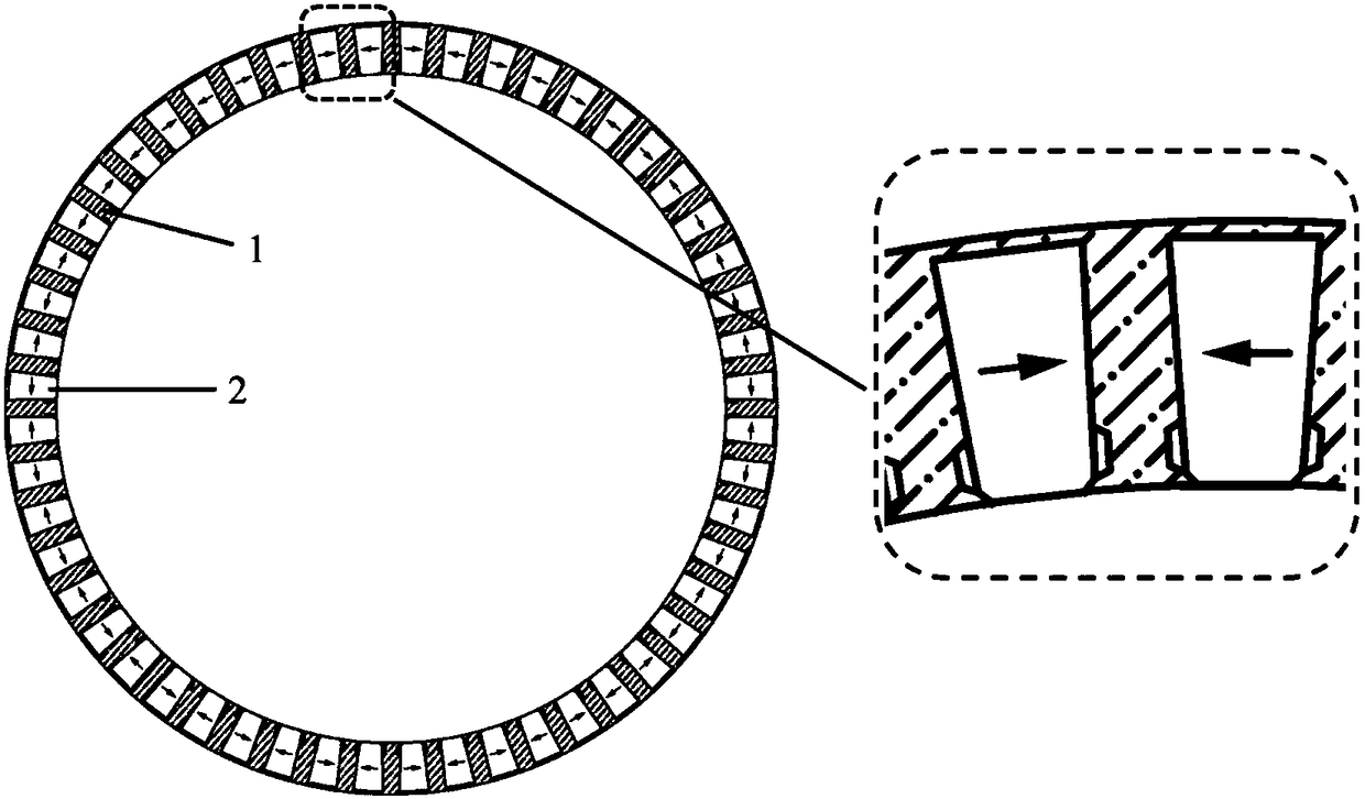
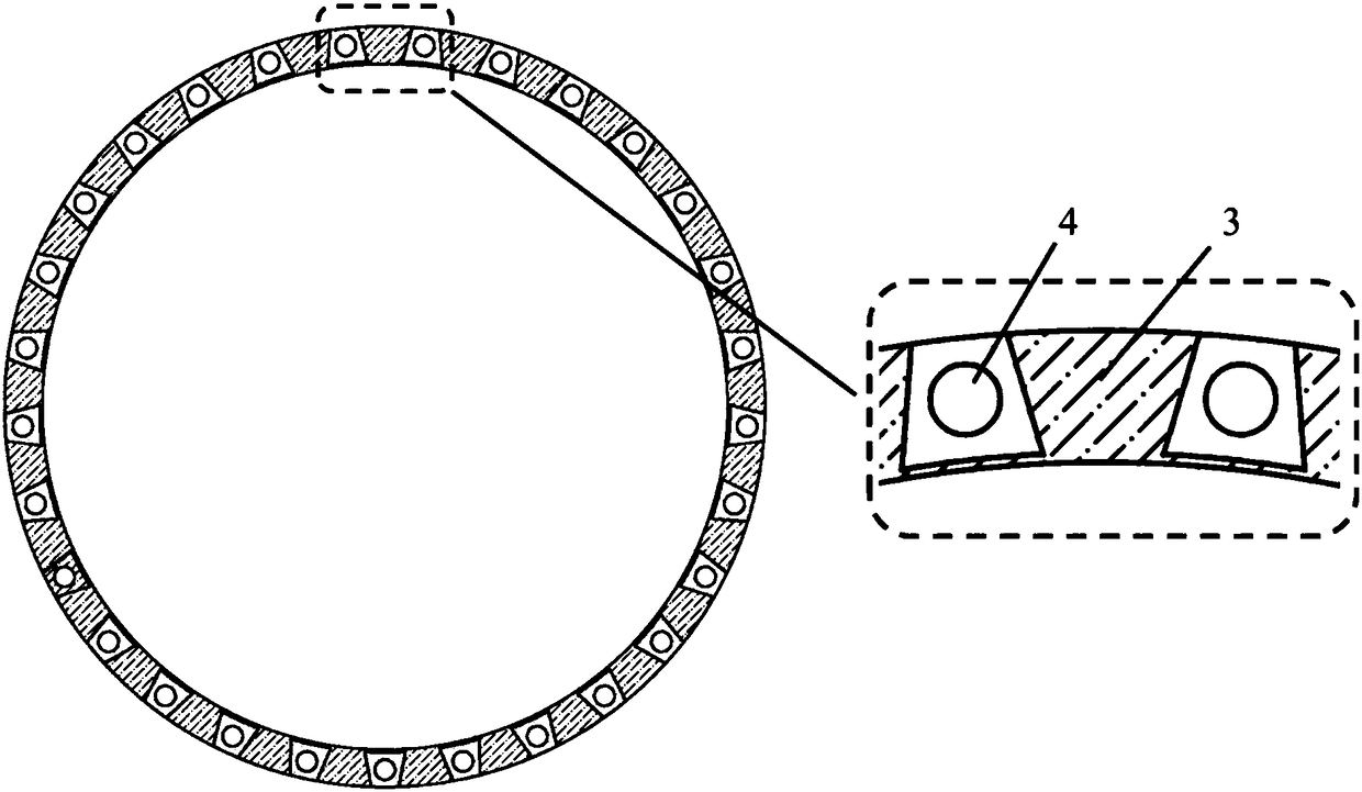
The invention discloses a high torque density magnetic field modulation type magnetic gear, which comprises a permanent magnetic outer stator, a modulation rotor and a permanent magnetic inner rotor which are concentrically nested to one another and arranged sequentially from outside to inside; air gaps are formed between the permanent magnetic outer stator and the modulation rotor as well as between the modulation rotor and the permanent magnetic inner rotor respectively; a trapezoidal groove is formed in the inner surface of an outer stator iron core of the permanent magnetic outer stator; demagnetization inhibition grooves are formed in the two sides of the inner end of the trapezoidal groove respectively; a tangentially polarized inverted trapezoidal outer stator permanent magnet is embedded in the trapezoidal groove; the demagnetization inhibition grooves have the action of inhibiting local demagnetization of the outer stator permanent magnet; the modulation rotor is composed of a plurality of magnet regulating yokes and a plurality of non-magnetic conductive materials embedded with punched holes respectively; the non-magnetic conductive materials embedded with the punched holes are embedded between two adjacent magnet regulating yokes respectively; the permanent magnetic inner rotor is composed of inner rotor permanent magnets and an inner rotor iron core which are concentrically nested to one another sequentially from outside to inside; and the inner rotor permanent magnets have a simplified Halbach structure. According to the magnetic field modulation type magnetic gear provided by the invention, higher torque density is realized under low torque ripples.

Description

technical field [0001] The invention belongs to the technical field of magnetic transmission, and more specifically relates to a magnetic field modulation type magnetic gear with high torque density. Background technique [0002] The idea of ​​a magnetic gear was proposed as early as the early 20th century. Its structure imitates that of a mechanical gear, and the attraction between magnetic poles is used instead of the meshing of mechanical teeth. Before the 1980s, due to the poor performance of ferrite permanent magnet materials, its transmission performance was poor, its practicability was not high, and its development was relatively slow. With the invention of high-performance permanent magnets in the 1980s, the output torque of magnetic gears has become considerable. In 2001, K.Atallah and D.Howe of the University of Sheffield in the United Kingdom proposed a concentric magnetic field modulation type magnetic gear (K.Atallah, D.Howe. A novel high-performance magnetic g...

Claims


Application Information

Patent Timeline
Patent Type & Authority Patents(China)
IPC IPC(8): H02K49/10
CPCH02K49/102H02K49/106
Inventor 曲荣海黄海林李大伟井立兵
Owner HUAZHONG UNIV OF SCI & TECH
Learn More