Hardware-in-loop test method and system

A test method and test system technology, applied in the direction of test/monitoring control system, transmission system, general control system, etc., can solve problems such as time-consuming and manpower-consuming, delayed test progress, and function errors, so as to improve test efficiency and improve Overall efficiency, the effect of ensuring integrity

Inactive Publication Date: 2015-08-19
BEIJING BORGWARD AUTOMOBILE CO LTD
View PDF7 Cites 14 Cited by
  • Summary
  • Abstract
  • Description
  • Claims
  • Application Information

AI Technical Summary

Problems solved by technology

[0006] During the test, the environment model responds improperly due to a certain part of the VCU’s function going wrong. It is necessary to wait until the VCU model is re-modified before testing. In addition, the environment model is relatively large and involves the engine, battery, motor, BMS, MCU, EMS, etc. , during the test process, due to improper transmission of a certain signal of the environmental model, it is necessary to wait until the environmental model is modified, then recompile, and then download it into the test equipment to continue the test, which will consume a lot of time and manpower, and delay the test progress

Method used


Image

  • Hardware-in-loop test method and system
  • Hardware-in-loop test method and system
  • Hardware-in-loop test method and system

Examples


Embodiment 1

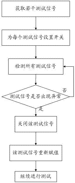
[0052] In this embodiment, a hardware-in-the-loop testing method is provided, and the flow chart is as follows figure 1 shown, including the following steps:

[0053]First, acquire several test signals and set switches for each test signal. The test signal here comes from the test system. For example, in the test system, the test signal comes from the virtual engine controller ECU, and the test signal is input into the running support environment RTI of the test system for testing. In this step, a switch is set for part or all of the signals from the engine controller ECU. The function of this switch is to turn off the signal. After the signal is turned off, it will not be able to be input into the running support environment RTI. However, However, the signal can be reassigned manually.

[0054] As other alternative implementation manners, the test signal for setting the switch here may be a CAN signal, an IO signal and any other signal that needs to be tested during the te...

Embodiment 2

[0059] On the basis of the foregoing embodiment 1, this embodiment provides a specific manner of acquiring several test signals and setting a switch for each test signal. The test signals selected here are selected according to the needs. For which signals you want to manually assign values, configure for which signals. In this embodiment, a configuration method for CAN signals and a configuration method for IO signals are provided. In other implementation manners, the CAN signal or the IO signal may be configured separately, or both may be configured simultaneously. Which signals are configured, which signals can be manually turned off and assigned later.

[0060] The process of configuring for CAN signals is as follows:

[0061] First, obtain the CAN protocol standard file, that is, the DBC file, which is the database file with the suffix DBC. The information in the DBC file includes the number of controllers in the CAN network, which controllers are there, which messages...

Embodiment 3

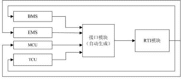
[0070] In this embodiment, a specific application example of the hardware-in-the-loop test method is provided. The test system is constructed by setting up an environment model. In the construction, an interface module needs to be set. The calls to automatically generate modules, which are then applied to the environment model.

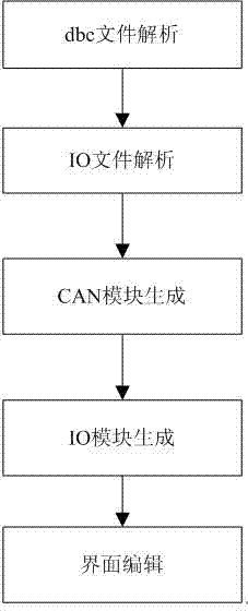
[0071] In the interface module, the switch of the CAN signal and the switch of the IO signal can be automatically generated, the process is as follows figure 2 As shown, the automatic generation program writing includes the following steps:

[0072] 1) Implement dbc file parsing. Import the dbc file and extract the information in the DBC file, including the number of controllers in the CAN network, which controllers are there, which messages are there, which controllers each message belongs to, and which signals are in the messages. Use M language to write a program to extract dbc file information, find the length of dbc, filter useful information,...


PUM


Abstract

The invention provides a hardware-in-loop test method and system. The method comprises the steps of: firstly, obtaining a plurality of test signals and setting a switch for at least one test signal; and then detecting all the test signals and judging whether the test signal with the set switch is abnormal, switching off the test signal in case of abnormity, cutting off the abnormal signal, reassigning the test signal, and continuing the test. In the scheme, a switch is set for each test signal, if some test signal is abnormal in the test process, the test signal is switched off, the abnormal test signal is cut off and reassigned with a suitable value, and the test goes on. In this way, the problem in the prior art that the downloading test is needed to be performed again after the abnormal signal is handled is solved; and by means of manual assignment, the influence of the abnormal signal to the test is prevented temporarily, other signals are tested, and the abnormal signal can be tested subsequently, so that the integral efficiency of the test is improved.

Description

technical field [0001] The invention relates to the field of new energy vehicle controller testing, in particular to a method and system for hardware-in-the-loop testing. Background technique [0002] With the development and popularization of automobile technology, more and more automobiles are owned, and the environmental problems caused by them are becoming more and more prominent. New energy vehicles are widely considered to be one of the main ways to solve problems such as vehicle exhaust pollution and oil energy shortage. The power system of a new energy vehicle mainly includes a power battery, a power battery management system (BMS, Battery Management System), a drive motor, a motor controller (MCU, Motor Control Unit), and a vehicle controller (VCU, Vehicle Control Unit) , engine, and engine controller (ECU, Electronic Control Unit). With the rapid development of new energy vehicles, the product performance and reliability requirements of the core components of its...

Claims


Application Information

Patent Timeline
Patent Type & Authority Applications(China)
IPC IPC(8): G05B23/02H04L29/06
CPCG05B23/0278H04L67/00
Inventor 荀野
Owner BEIJING BORGWARD AUTOMOBILE CO LTD
Why Eureka
Try Eureka