Monitoring equipment layout method and device

A technology of monitoring equipment and layout methods, which is applied in the direction of instruments, closed-circuit television systems, computing, etc., can solve the problems of inability to control human risks and over-reliance on construction personnel for quality

Active Publication Date: 2015-08-19
SHENZHEN SHUNHENGLI TECH ENG CO LTD
View PDF4 Cites 30 Cited by
  • Summary
  • Abstract
  • Description
  • Claims
  • Application Information

AI Technical Summary

Problems solved by technology

[0007] In view of this, the technical problem to be solved by the present invention is to provide a monitoring equipment layout method and device to solve the technical problem that the final quality of the project depends too much on the technical level and experience of the construction personnel and cannot control the artificial risk

Method used


Image

  • Monitoring equipment layout method and device
  • Monitoring equipment layout method and device
  • Monitoring equipment layout method and device

Examples


Embodiment 1

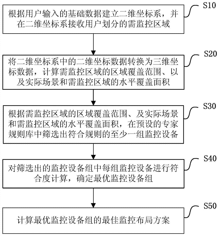
[0073] Such as figure 1 As shown, a monitoring device layout method provided by an embodiment of the present invention includes the following steps:

[0074] S10. Establish a two-dimensional coordinate system according to the basic data input by the user, and receive the area to be monitored divided by the user in the two-dimensional coordinate system.

[0075] Specifically, the user inputs basic data through the man-machine interface of the client, and the basic data includes the two-dimensional plan of the actual scene, the actual height H of the scene, and the scaling ratio R. Here it is necessary to ensure that the two-dimensional floor plan matches the proportion of the actual scene. The client establishes a two-dimensional coordinate system on the two-dimensional plan according to the input basic data, and the user divides the scope of the area to be monitored on the two-dimensional plan of the established two-dimensional coordinate system. Among them, the division of t...

Embodiment 2

[0113] Such as Figure 4 As shown, a device screening method provided by a preferred embodiment of the present invention includes the following steps:

[0114] S401. Calculate the spatial coverage of the area to be monitored.

[0115] Specifically, the approximate range of the scene can be obtained by cutting the actual scene into N small cuboids, calculating the ranges of each small cuboid and adding them up, which is consistent with the principle of the method for calculating the area in step S20, and the calculation is performed according to the following formula. Spatial coverage V of the area:

[0116] V = Σ i = 1 N dx i dy i dz i And (0

[0117] Among them, dx i ,dy i ,dz i respectively represent the length, width and height of each small ...

Embodiment 3

[0151] Such as Figure 6 As shown, a monitoring equipment layout system provided by a preferred embodiment of the present invention includes a receiving module 10, a data conversion module 20, a monitoring equipment screening module 30, a layout determination module 40 and a simulation module 50, wherein:

[0152] The receiving module 10 is configured to establish a two-dimensional coordinate system according to the basic data input by the user, and receive the area to be monitored divided by the user in the two-dimensional coordinate system.

[0153] Specifically, the user inputs basic data through the man-machine interface of the client, and the basic data includes the two-dimensional plan of the actual scene, the actual height H of the scene, and the zoom ratio P. Here it is necessary to ensure that the two-dimensional floor plan matches the proportion of the actual scene. The client establishes a coordinate system on the two-dimensional plan according to the input basic d...


PUM


Abstract

The invention discloses a monitoring equipment layout method and device and belongs to the field of monitoring. The method comprises: establishing a two-dimensional coordinate system according to basic data input by a user, and receiving a region that needs to be monitored, which is divided by a user, through the two-dimensional coordinate system; converting two-dimensional coordinate data in the two-dimensional coordinate system into three-dimensional coordinate data; calculating a region covering range of the region that needs to be monitored, an actual scene and a horizontal coverage area of the region that needs to be monitored; screening at least one group of monitoring equipment meeting rules from a pre-set specialist rule base according to the region covering range of the region that needs to be monitored, the actual scene and the horizontal coverage area of the region that needs to be monitored; determining the conformity of each group of the monitoring equipment in the screened monitoring equipment group, and determining an optimal monitoring equipment group; and calculating an optimal monitoring layout scheme of the optimal monitoring equipment group. With the adoption of the monitoring equipment layout method and device, the optimal layout scheme can be rapidly, directly and accurately simulated, so that the excessive dependence on the technological level and experiences of constructors is avoided; and the quality of projects can be ensured and the layout efficiency can be improved. Moreover, the monitoring equipment can be sufficiently utilized and the cost is saved.

Description

technical field [0001] The present invention relates to the monitoring field, in particular to a monitoring equipment layout method and device. Background technique [0002] With the advancement of technology and the improvement of people's safety awareness, the application of monitoring equipment has become a necessity. Although monitoring equipment has been used in large quantities, the installation and deployment are still at the traditional stage. For example, when monitoring design and deployment in a building or an area, due to the differences in field conditions, it is often only based on experience and simple calculations. Layout design may be able to meet the requirements of users in small areas with low safety requirements. However, in complex building environments, such as government office halls, large shopping malls, and office buildings, there are many entrances and exits, complex personnel, frequent access, and mobility. Strong, this design and installation m...

Claims


Application Information

Patent Timeline
Patent Type & Authority Applications(China)
IPC IPC(8): G06F17/50H04N7/18
Inventor 吴健龙
Owner SHENZHEN SHUNHENGLI TECH ENG CO LTD
Why Eureka
Try Eureka