Device used to monitor bolt fracture or looseness

A bolt and monitoring plate technology is applied in the field of devices for monitoring bolt breakage or loosening, which can solve the problems that the device cannot play a monitoring role, cannot monitor the bolt structure, is prone to corrosion or oxidation, etc., and achieves simple structure, wide monitoring range, The effect of saving manpower and material resources

Inactive Publication Date: 2015-08-19
CHONGQING UNIV
View PDF5 Cites 22 Cited by
  • Summary
  • Abstract
  • Description
  • Claims
  • Application Information

AI Technical Summary

Problems solved by technology

[0003] 1. Since the upward movement of the nut is very irregular when the nut is loose, if the nut does not touch the two pieces of iron at the same time during the upward movement, the device cannot play a monitoring role
[0004] 2. The nut and the two iron sheets in the monitoring device are in direct contact with the atmosphere, which is prone to corrosion or oxidation, which will cause the circuit to fail to connect when the nut is loose, so the detection of the device is not accurate enough
[0005] 3. The monitoring device is installed on the screw rod of the bolt as a whole. It cannot monitor the bolt structure that is directly screwed on the base and the bolt tail is not exposed, nor can it monitor the situation of bolt breakage. Bolt breakage often occurs and is more dangerous.

Method used


Image

  • Device used to monitor bolt fracture or looseness
  • Device used to monitor bolt fracture or looseness
  • Device used to monitor bolt fracture or looseness

Examples


Embodiment 1

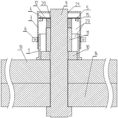
[0030] Such as figure 1 The shown device for monitoring bolt breakage or loosening includes a cylindrical housing, the lower part of which is made of insulating material, and a hollow space with a lower end opening and a diameter greater than that of the washer 10 is provided in the housing. cavity 23, and the tail of the bolt 9 and the washer 10, fastening nut 11 and locknut 12 arranged on the bolt 9 are all located in the cavity 23, and also includes a monitoring circuit, which includes a power supply 26, a switch assembly, The resistor 27 connected to the positive pole of the power supply 26, the output terminal 29 connected to the resistor 27, the connection point of the resistor 27 and the output terminal 29 is connected to one end of the switch assembly, and the other end of the switch assembly is grounded. The switch assembly includes a monitoring plate 4 arranged on the upper end surface of the locknut 12, a trigger structure fixed in the middle or upper part of the ca...

Embodiment 2

[0035] Such as Figure 6 to Figure 8 As shown, the difference between this embodiment and Embodiment 1 is that a normally open switch is formed between the monitoring board 4 and the trigger structure, and the locknut 12 moves upward with the monitoring board 4 to make the switch assembly turn on. The trigger structure is a ring plate 17 fixed on the top wall of the cavity 23 and parallel to the monitoring board 4 .

[0036] Specifically, the ring plate 17 is conductive and connected to the resistor 27 , the monitoring board 4 is conductive and grounded, and the center of the ring plate 17 is provided with a third through hole 22 through which the bolt 9 can pass. The ring plate 17 is fixed on the top wall of the cavity 23 by four second screws 18; the second screws 18 are provided with second nuts 19, and the distance between the monitoring plate 4 and the ring plate 17 is 0.5-2mm after installation. In particular, the diameters of the first through hole 20 and the third thr...

Embodiment 3

[0041] Such as Figure 10 As shown, the difference between the present embodiment and the first embodiment is that the bolt 9 passes through the fastened member 13 and is installed on the base 14 by threading, and the tail of the bolt 9 is located in the base 14 at this time. The bolt head 33 is located in the cavity 23 , and the monitoring board 4 is arranged on the bolt head 33 . When the bolt 9 becomes loose or broken, the bolt head 33 will move upward with the monitoring board 4, and the U-shaped wire 5 will be pulled off, the ground terminal of the monitoring circuit will be disconnected, and the external output level signal state will be will change, so that the bolt 9 is known to be faulty. The triggering structure and monitoring circuit in this embodiment can also be changed to the triggering structure and monitoring circuit described in the second embodiment.


PUM


Abstract

The invention relates to a device used to monitor bolt fracture or looseness. The device comprises a housing in a cylindrical shape. The lower part of the housing is made of an insulating material. The housing is internally provided with a cavity which is provided with an opening on the lower end, and the device also comprises a monitoring circuit. The monitoring circuit comprises a power supply, a switch assembly, a resistor connected with the anode of a power supply, and an output end connected with the resistor. The connecting point of the resistor and the output end is connected with one end of the switch assembly. The other end of the switch assembly is connected with ground. The switch assembly comprises a monitoring plate arranged on the head of a locknut or a bolt, and a trigger structure fixed in the cavity. A plurality of series-connected normally-closed switches or a plurality of parallel-connected normally-open switches are formed between the monitoring plate and the trigger structure. The device is simple in structure, convenient in installation, low in cost, wide in monitoring range, high in monitoring precision, and low in power consumption of the monitoring circuit, and sensitive in response. Using the device, manual polling is not needed, and output signals are monitored after the device is installed, thereby greatly improving working efficiency, and saving manpower and material resources.

Description

technical field [0001] The invention relates to monitoring equipment for bolts, in particular to a device for monitoring broken or loose bolts. Background technique [0002] Large bolts and nuts are used in many fields, such as rail transit, large machinery, building construction, etc. Generally, the bolts pass through the base and the fastened parts, and the fastened parts are fixed on the base through washers, fastening nuts and locknuts. In the normal operation process, due to various reasons such as impact, the bolts are prone to breakage, and the fastening nuts or locknuts are loose, which has caused serious safety hazards to the lives of the staff. The detection of bolt breakage and looseness is mostly manual inspection, which has a large workload, time-consuming and high cost. Moreover, the installation structure of many bolts is special, the stress situation is complicated, and the number of detections is huge, which makes the detection of bolts more complicated an...

Claims


Application Information

Patent Timeline
Patent Type & Authority Applications(China)
IPC IPC(8): G08B21/18
CPCG08B21/187
Inventor 叶俊勇文枰汪同庆姜平
Owner CHONGQING UNIV
Why Eureka
Try Eureka