
Coplanar waveguide fed broadband circularly polarized antenna

A circularly polarized antenna and coplanar waveguide technology, applied in the field of communication, can solve problems such as cumbersome adjustment process, and achieve the effect of convenient switching

Inactive Publication Date: 2015-08-19
ANQING NORMAL UNIV
View PDF1 Cites 8 Cited by
  • Summary
  • Abstract
  • Description
  • Claims
  • Application Information

AI Technical Summary

Problems solved by technology

The parameters and position of the T-shaped microstrip of this coplanar waveguide antenna need to be adjusted, and the adjustment process is very cumbersome

Method used


Image

  • Coplanar waveguide fed broadband circularly polarized antenna
  • Coplanar waveguide fed broadband circularly polarized antenna

Examples


Embodiment 1

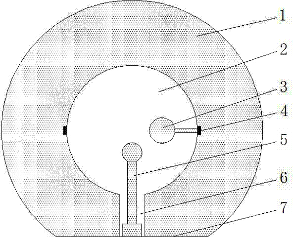
[0021] Such as figure 1 Shown, a kind of broadband circularly polarized antenna fed by a coplanar waveguide, the antenna includes a relative permittivity of 4.5, a height of 1.6 mm, a diameter of 80 mm circular dielectric substrate 1, the circular dielectric The bottom of the substrate 1 is cut along a horizontal tangent line 7, the distance between the horizontal tangent line 7 and the center of the circular dielectric substrate 1 is 2 / 3 of the side length of the substrate, and the middle part of the dielectric substrate 1 is provided with a circle with a center diameter of 40 mm. Groove 2, the bottom edge of the circular groove 2 is provided with a slit 6 with a width of 6.4 mm along the direction of the vertical horizontal tangent 7, and a vertical strip 5 extending into the circular groove 2 is provided in the slit 6, so One end of the vertical strip 5 located on the horizontal tangent line 7 is a rectangular sheet, and the other end is a circular sheet. The center of both...

Embodiment 2

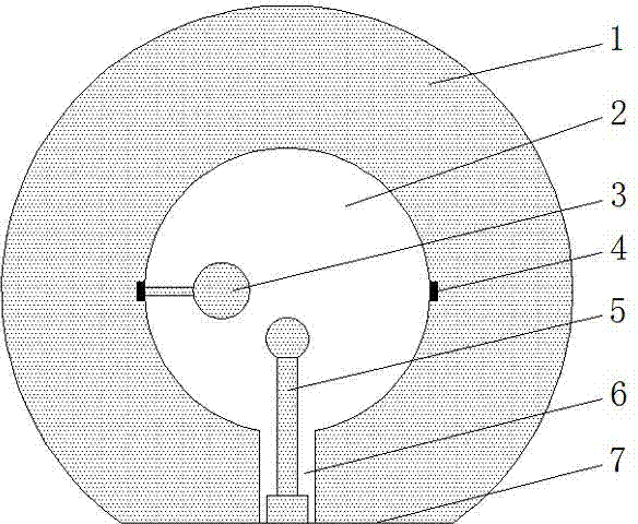
[0023] As described in Example 1, the difference is as figure 2 As shown, the horizontal strip 3 is connected to the inlet 4 on the left side of the circular groove 2 .

[0024] The invention utilizes the horizontal strip and the vertical strip to form a pair of degenerate modes to realize the circular polarization characteristic; through the access ports on both sides of the circular groove, the switching between left-handed and right-handed circular polarization can be conveniently performed.


PUM


Abstract

The present invention discloses a coplanar waveguide fed broadband circularly polarized antenna. The antenna comprises a circular dielectric substrate, the bottom part of the circular dielectric substrate is cut off along a flat tangent, a circular groove with the same circle center as the circular dielectric substrate is formed in the middle part of the circular dielectric substrate, a notch is formed along a direction perpendicular to the flat tangent at the edge of the bottom part of the circular groove, a vertical strap stretching into the circular groove is disposed in the notch, one end of the vertical strap on the flat tangent is a rectangular piece while the other end is a round piece, access entries are formed at centers of two side faces of the circular groove, one side face is connected through the access entry with a horizontal strap stretching into the circular groove, and one end of the horizontal strap inside the circular groove is a round metal piece. The horizontal strap is connected on the side face of the circular groove and thus forms an orthogonal degenerate mode with a 90-degree phase difference with the vertical strap, thereby realizing the circular polarization feature; and the horizontal strap are connected to the access entries at the two sides of the circular groove, such that switching between left-handed circular polarization and right-handed circular polarization can be conveniently realized.

Description

technical field [0001] The invention relates to the technical field of communication, in particular to a broadband circularly polarized antenna fed by a coplanar waveguide in wireless communication. Background technique [0002] Coplanar waveguide-fed planar wire is easy to integrate with active devices because its radiation unit and feed unit are on the same plane, and it is easy to realize multiple feeding methods such as broadband and direct connection, inductive coupling and capacitive coupling. Applications in wireless communication have been receiving great attention. Coplanar waveguide antennas are often used to achieve ultra-wideband characteristics of antenna impedance, but reports on circularly polarized planar antennas fed by coplanar waveguides are rare. Someone proposed that the printed board planar circularly polarized antenna realized by coplanar waveguide feeding has broadband characteristics, and adopts the square slot structure fed by coplanar waveguide, a...

Claims


Application Information

Patent Timeline
Patent Type & Authority Applications(China)
IPC IPC(8): H01Q1/38H01Q9/04
Inventor 周华
Owner ANQING NORMAL UNIV
Learn More