
Eureka
For R&D, Eureka makes reading and utilizing patents & technical documents easy.
Eureka AIR
Designed for self-driven R&D workflows. Generate viable solutions, solve complex R&D challenges, empower your innovation with AI.

Eureka Materials
Designed for material experts only. Revolutionize your material R&D, from search, analyze, to developing new materials.

TechResearch
Generate reliable direction feasibility study reports for your R&D in just a few steps.

TechSeek
Discover and master advanced knowledge NOW. Basics, ideas, possibilities, all at once.

TechMind
As an expert in R&D Theories, TechMind can generates customized viable solutions instantly.

TechRisk
Analyze your overall solution with one click, know your potential R&D risks in advance.

TechMonitor
Get weekly tech updates, stay abreast of the latest tech innovations and key insights.
Interference suppression device and method, and receiver
An interference suppression device, a technology of spatial covariance, applied to the shaping network in the transmitter/receiver, preventing/detecting errors through diversity reception, spatial transmit diversity, etc., to achieve the effect of ensuring performance
- Summary
- Abstract
- Description
- Claims
- Application Information
AI Technical Summary
Problems solved by technology
Method used
Image

Examples
Embodiment 1
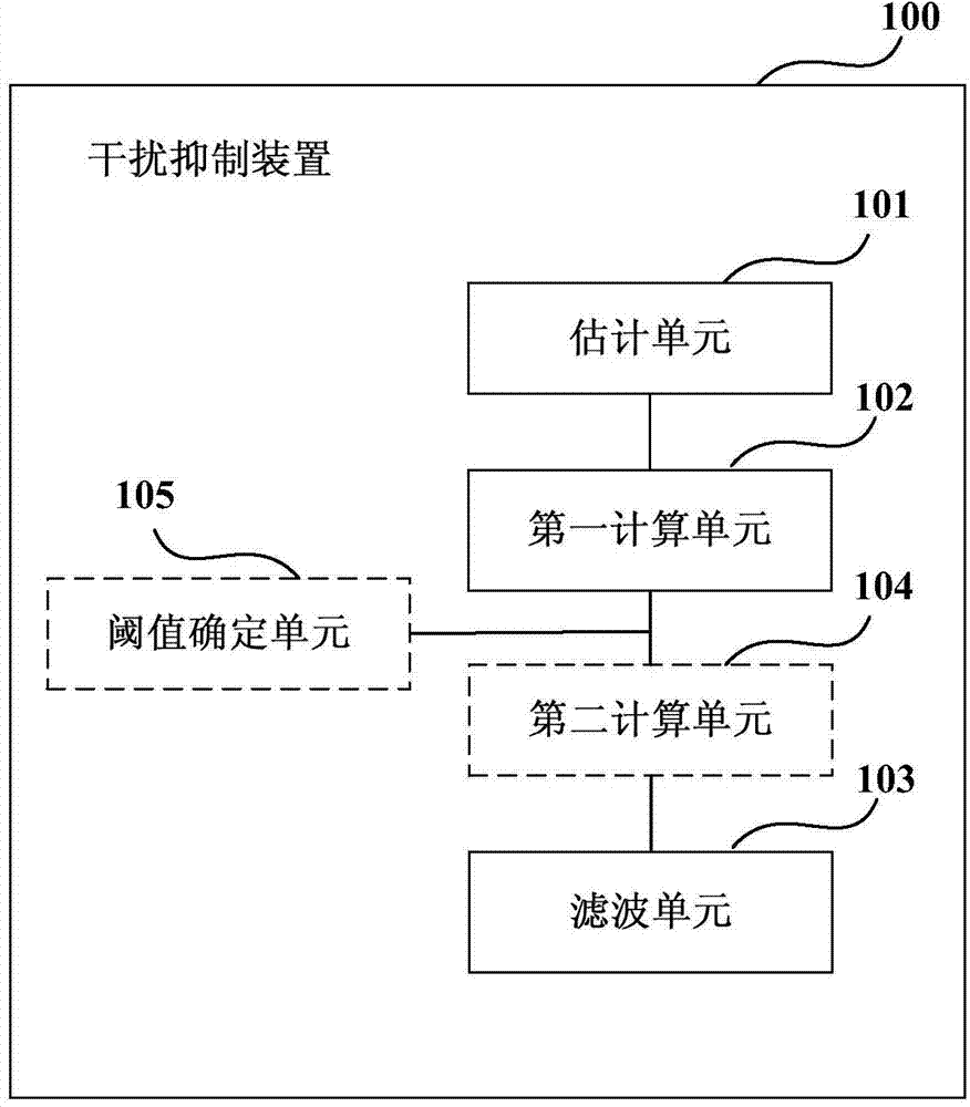
[0025] figure 1 is a schematic structural diagram of the interference suppression device according to Embodiment 1 of the present invention. Such as figure 1 As shown, the device 100 includes: an estimation unit 101, a first calculation unit 102, and a filtering unit 103, wherein,
[0026] The estimation unit 101 is configured to estimate the interference and noise spatial covariance matrix of each area of the transmission bandwidth, where the area refers to a time-frequency region including at least one physical resource block in the frequency domain and at least one subframe in the time domain scope;
[0027] The first calculation unit 102 is configured to calculate a metric value according to the estimated interference and noise spatial covariance matrix of each area, where the metric value reflects the level of the interference-to-noise ratio within the transmission bandwidth;
[0028] The filtering unit 103 is configured to perform whitening filtering on received dat...
Embodiment 2
[0109] Image 6 is a schematic diagram of the structure of the receiver in Embodiment 2 of the present invention, such as Image 6 As shown, the receiver 600 includes an interference suppression device 601. The structure and function of the interference suppression device 601 are the same as those described in Embodiment 1, and will not be repeated here.
[0110] Figure 7 It is a schematic block diagram of the system configuration of the receiver 700 according to Embodiment 2 of the present invention. Such as Figure 7 As shown, the receiver 700 may include a central processing unit 701 and a memory 702 ; the memory 702 is coupled to the central processing unit 701 . This diagram is exemplary; other types of structures may also be used in addition to or in place of this structure, for telecommunications or other functions.
[0111] Such as Figure 7 As shown, the electronic device 700 may further include: a communication module 703 , an input unit 704 , a display 705 , a...
Embodiment 3
[0122] Figure 8 is a flow chart of the interference suppression method in Embodiment 3 of the present invention, corresponding to the interference suppression device in Embodiment 1. Such as Figure 8 As shown, the method includes:
[0123] Step 801: Estimate the interference and noise spatial covariance matrix of each area of the transmission bandwidth, where the area refers to a time-frequency range including at least one physical resource block in the frequency domain and at least one subframe in the time domain;
[0124] Step 802: Calculate a metric value according to the estimated interference and noise spatial covariance matrix of each area, where the metric value reflects the level of the interference-to-noise ratio within the transmission bandwidth;
[0125] Step 803: When the metric value is greater than a preset threshold, perform whitening filtering on the received data and / or channel.
[0126] In this embodiment, the method of estimating the interference and ...
PUM
 Abstract
Description
Claims
Application Information
 - R&D Engineer
- R&D Manager
- IP Professional
- Industry Leading Data Capabilities
- Powerful AI technology
- Patent DNA Extraction
Browse by: Latest US Patents, China's latest patents, Technical Efficacy Thesaurus, Application Domain, Technology Topic, Popular Technical Reports.
© 2024 PatSnap. All rights reserved.Legal|Privacy policy|Modern Slavery Act Transparency Statement|Sitemap|About US| Contact US: help@patsnap.com