
Method for preparing silica gel diaphragm and silica gel diaphragm

A silicone diaphragm, liquid silicone technology, applied in the direction of diaphragm fixation/tightening, flat diaphragm, polymer material diaphragm, etc., can solve the problems of thick diaphragm thickness, limited injection molding conditions, high cost, and achieve vibration The effect of various membrane forms, simple molding methods, and controllable diaphragm thickness

Active Publication Date: 2015-08-19
GOERTEK INC
View PDF3 Cites 12 Cited by
  • Summary
  • Abstract
  • Description
  • Claims
  • Application Information

AI Technical Summary

Problems solved by technology

[0002] The current silicone diaphragm is usually molded by injection molding. This molding method not only has high cost and low efficiency, but also is limited by injection molding conditions. The thickness of the diaphragm is relatively thick, usually above 50 μm.
In addition, during the injection molding process, the mold adjustment is complicated, which is not conducive to the rapid development of products

Method used


Image

  • Method for preparing silica gel diaphragm and silica gel diaphragm
  • Method for preparing silica gel diaphragm and silica gel diaphragm
  • Method for preparing silica gel diaphragm and silica gel diaphragm

Examples


Embodiment Construction

[0040] In order to make the object, technical solution and advantages of the present invention clearer, the implementation manner of the present invention will be further described in detail below in conjunction with the accompanying drawings.

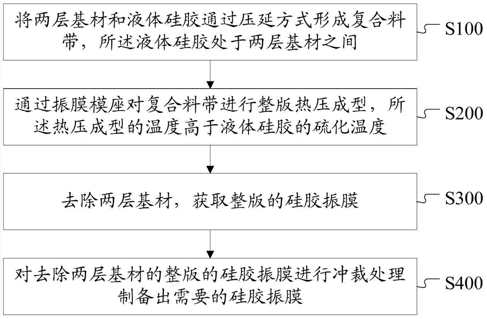
[0041] figure 1 A flow chart of a method for preparing a silica gel diaphragm provided by an embodiment of the present invention, the method includes:

[0042] S100, forming a composite tape by calendering two layers of substrates and liquid silica gel, and the liquid silica gel is located between the two layers of substrates.

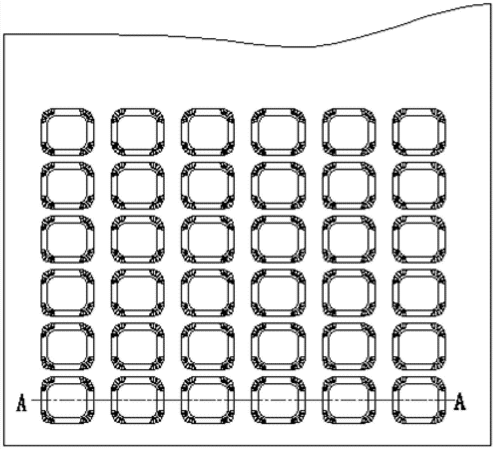
[0043] Such as figure 2 As shown, it is a schematic diagram of the composite tape prepared by calendering provided by the embodiment of the present invention, and the liquid silica gel in the figure is between the upper substrate and the lower substrate.

[0044] Among them, calendering refers to the process of making semi-finished products such as film through the nip between two rollers that are relatively...


PUM

PropertyMeasurementUnit
heat deflection temperatureaaaaaaaaaa

Abstract

The invention discloses a method for preparing a silica gel diaphragm and the silica gel diaphragm. The method comprises: forming a composite material tape by two layers of substrates and liquid silica gel through a calendering method, the liquid silica gel being between the two layers of substrates; performing full-plate hot press molding on the composite material tape through a diaphragm die holder, temperature of the hot press molding being higher than vulcanizing temperature of the liquid silica gel; removing the two layers of substrates, to obtain a full-plate silica gel diaphragm; and performing blanking on the full-plate silica gel diaphragm from which the two layers of substrates are removed, so as to prepare a required silica gel diaphragm. Compared with a conventional scheme, the technical scheme is advantaged by simple forming method, low cost, diverse diaphragm forms, and thin diaphragm thickness.

Description

technical field [0001] The invention relates to the technical field of electronic products, in particular to a method for preparing a silica gel diaphragm and the silica gel diaphragm. Background technique [0002] The current silicone diaphragm is usually molded by injection molding. This molding method not only has high cost and low efficiency, but also is limited by injection molding conditions, and the thickness of the diaphragm is relatively thick, usually above 50 μm. In addition, during the injection molding process, the mold adjustment is complicated, which is not conducive to the rapid development of products. Contents of the invention [0003] In view of the above-mentioned problems, the present invention is proposed in order to provide a method for preparing a silica gel diaphragm and a silica gel diaphragm that overcomes the above-mentioned problems or at least partially solves the above-mentioned problems. The technical solution of the present invention is ach...

Claims


Application Information

Patent Timeline
Patent Type & Authority Applications(China)
IPC IPC(8): H04R31/00
CPCH04R7/10H04R7/18H04R2307/023B29C43/24B29C43/28B29K2105/0061B29L2031/38H04R31/003B29C43/245B29C43/30B29C43/58H04R7/06H04R2307/025
Inventor 郭晓冬王文海
Owner GOERTEK INC
Learn More